Installation method of blade

An installation method and blade technology, applied in the direction of rotary cutting tools, wood processing appliances, manufacturing tools, etc., can solve the problems of high labor intensity, low efficiency, tool deformation, etc., and achieve a high degree of automation, easy installation, and good safety. Effect

Inactive Publication Date: 2018-06-19
成都恒成工具股份有限公司
View PDF9 Cites 2 Cited by
  • Summary
  • Abstract
  • Description
  • Claims
  • Application Information

AI Technical Summary

Problems solved by technology

At present, manual welding is generally used. There are many defects in manual welding: for example, it is difficult to grasp the temperature and time of welding. If the temperature is low or the time is short, the welding may not be firm; Too much tool deformation
The automatic welding machine for woodworking knives disclosed in this patent document can better control the welding temperature and time, ensure the welding quality, have a high level of automation, and is easy to operate. However, the knife body and the blade need to be manually adjusted when the knife body is installed. position, so that the blade is installed in the slot of the cutter body, the manual labor intensity is high and the efficiency is low; when the blade is installed, the blade needs to be manually removed for installation, and the manual labor intensity is high, not only poor in safety, but also low in efficiency

Method used


Image

  • Installation method of blade
  • Installation method of blade
  • Installation method of blade

Examples


Embodiment 1

[0050] A method for installing a blade, comprising the steps of:

[0051] a. Place the cutter body on the cutter holder;

[0052] b. Move the blade of the cutter body aligning device down and insert it into the slot of the cutter body, and drive the blade to rotate through the rotation of the stepping motor, so that the slot of the cutter body is aligned with the placement position of the blade in the next process. removed from the slot,

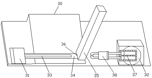
[0053] c. The blade is pushed out through the pusher cylinder of the blade placement device, the rotating cylinder drives the double-axis cylinder to rotate clockwise 90 degrees, the parallel clamp on the double-axis cylinder clamps the pushed blade and then rotates 90 degrees counterclockwise, and inserts the blade into the knife in the slot of the body.

[0054] This embodiment is the most basic implementation mode, "a. place the cutter body on the cutter holder; b. move down the insertion piece of the cutter body aligning device and ins...

Embodiment 2

[0056] A method for installing a blade, comprising the steps of:

[0057] a. Place the cutter body on the cutter holder;

[0058] b. Move the blade of the cutter body aligning device down and insert it into the slot of the cutter body, and drive the blade to rotate through the rotation of the stepping motor, so that the slot of the cutter body is aligned with the placement position of the blade in the next process. remove from the slot;

[0059] c. The blade is pushed out through the pusher cylinder of the blade placement device, the rotating cylinder drives the double-axis cylinder to rotate clockwise 90 degrees, the parallel clamp on the double-axis cylinder clamps the pushed blade and then rotates 90 degrees counterclockwise, and inserts the blade into the knife in the slot of the body.

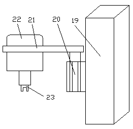
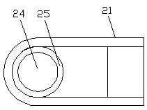
[0060] Described cutter body aligning device comprises support 19, is fixed with elevating cylinder 20 on the support 19, is fixedly connected with support 21 horizontally on the elevati...

Embodiment 3

[0065] A method for installing a blade, comprising the steps of:

[0066] a. Place the cutter body on the cutter holder;

[0067] b. Move the blade of the cutter body aligning device down and insert it into the slot of the cutter body, and drive the blade to rotate through the rotation of the stepping motor, so that the slot of the cutter body is aligned with the placement position of the blade in the next process. remove from the slot;

[0068] c. The blade is pushed out through the pusher cylinder of the blade placement device, the rotating cylinder drives the double-axis cylinder to rotate clockwise 90 degrees, the parallel clamp on the double-axis cylinder clamps the pushed blade and then rotates 90 degrees counterclockwise, and inserts the blade into the knife in the slot of the body.

[0069] Described cutter body aligning device comprises support 19, is fixed with elevating cylinder 20 on the support 19, is fixedly connected with support 21 horizontally on the elevati...


PUM


Abstract

The invention discloses an installation method of a blade. The installation method of the blade belongs to the technical field of cutter processing and preparing, and is characterized by comprising the following steps of a, placing a cutter body on a cutter clamping device; b, downwards moving an inserting plate of a cutter body alignment device, inserting the inserting plate into an inserting slot of the cutter body, rotating a stepping motor to drive the inserting plate to rotate, enabling the inserting slot of the cutter body to align at a placement position of a blade of a next process, upwards moving the inserting plate, and separating the inserting plate from the inserting slot; and c, pushing the blade out through a blade pushing air cylinder of a blade placement device, rotating the air cylinder to drive a double-shaft air cylinder to rotate clockwise at 90 degrees, clamping the pushed-out blade through a parallel clip on the double-shaft air cylinder, then anticlockwise rotating the blade at 90 degrees, and inserting the blade into the inserting slot of the cutter body. The installation method of the blade provided by the invention not only can be used for quickly aligningan installation position, corresponding to the blade, of the cutter body inserting slot, but also can be used for quickly taking the blade out for installing the blade, and is high in automation degree without the need for manual intervention, good in safety and high in efficiency.

Description

technical field [0001] The invention relates to the technical field of tool processing and preparation, in particular to a method for installing a blade. Background technique [0002] A cutting tool is a tool used for cutting in mechanical manufacturing, also known as a cutting tool. The vast majority of knives are for machine use, but some are also for hand use. Knives for cutting wood are called woodworking knives. Knives are usually composed of two parts: a blade and a cutter body. The blade is made of more expensive cemented carbide or high-speed steel. High-speed steel is a tool steel with high hardness, high wear resistance and high heat resistance, also known as high-speed tool steel or front steel, commonly known as white steel. The cutter body is made of ordinary steel, and the two parts are welded together with solder. At present, manual welding is generally used. There are many defects in manual welding: for example, it is difficult to grasp the temperature an...

Claims


Application Information

Patent Timeline
Patent Type & Authority Applications(China)
IPC IPC(8): B27G13/00
Inventor 金绍龙
Owner 成都恒成工具股份有限公司
Why Eureka
Try Eureka