Anti-loose roller cloth guide-unfolding stacking device

A fabric and loose technology, applied in the direction of winding strips, thin material handling, folding thin materials, etc., can solve the problem of single structure of the fabric guiding device, achieve better stacking effect, good continuity, and improve guiding efficiency Effect

Active Publication Date: 2018-06-19
南通格瑛纺织品有限公司
View PDF4 Cites 5 Cited by
  • Summary
  • Abstract
  • Description
  • Claims
  • Application Information

AI Technical Summary

Problems solved by technology

[0003] The purpose of the present invention is to provide a reel cloth guiding and stacking device with anti-loosening, which can effectively solve the problem of single structure of the cloth guiding device in the prior art; Conveying, stacking of fabrics and rolling of stacked fabrics can effectively improve the efficiency of fabric guiding and further processing of fabrics

Method used


Image

  • Anti-loose roller cloth guide-unfolding stacking device
  • Anti-loose roller cloth guide-unfolding stacking device
  • Anti-loose roller cloth guide-unfolding stacking device

Examples


specific Embodiment approach 1

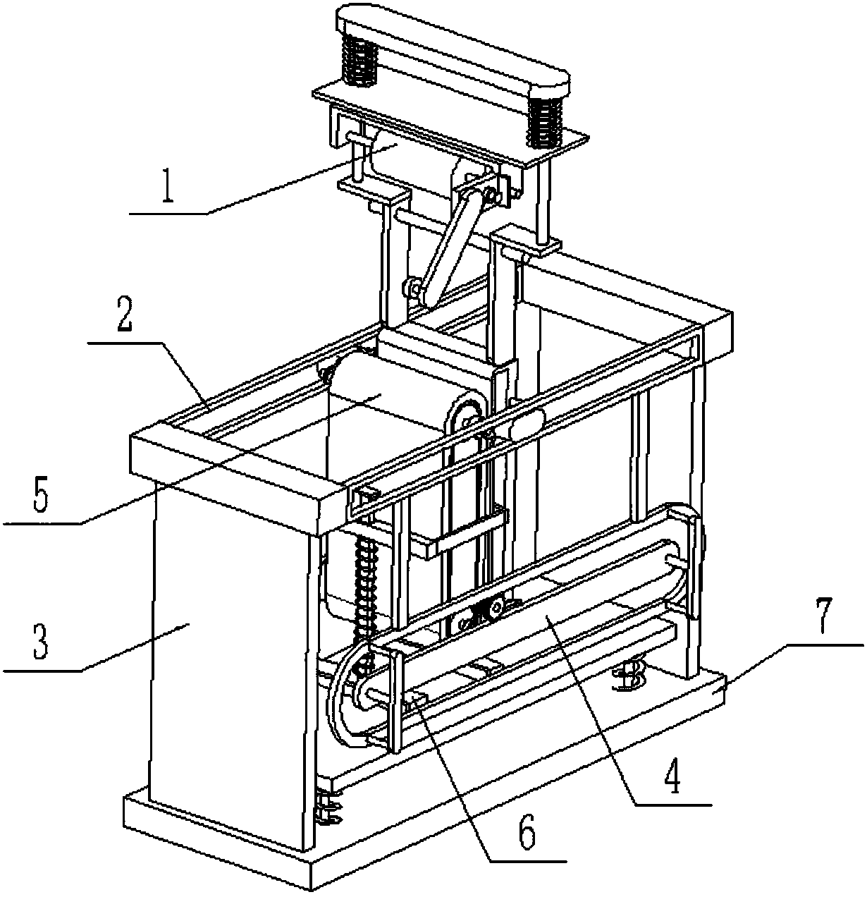
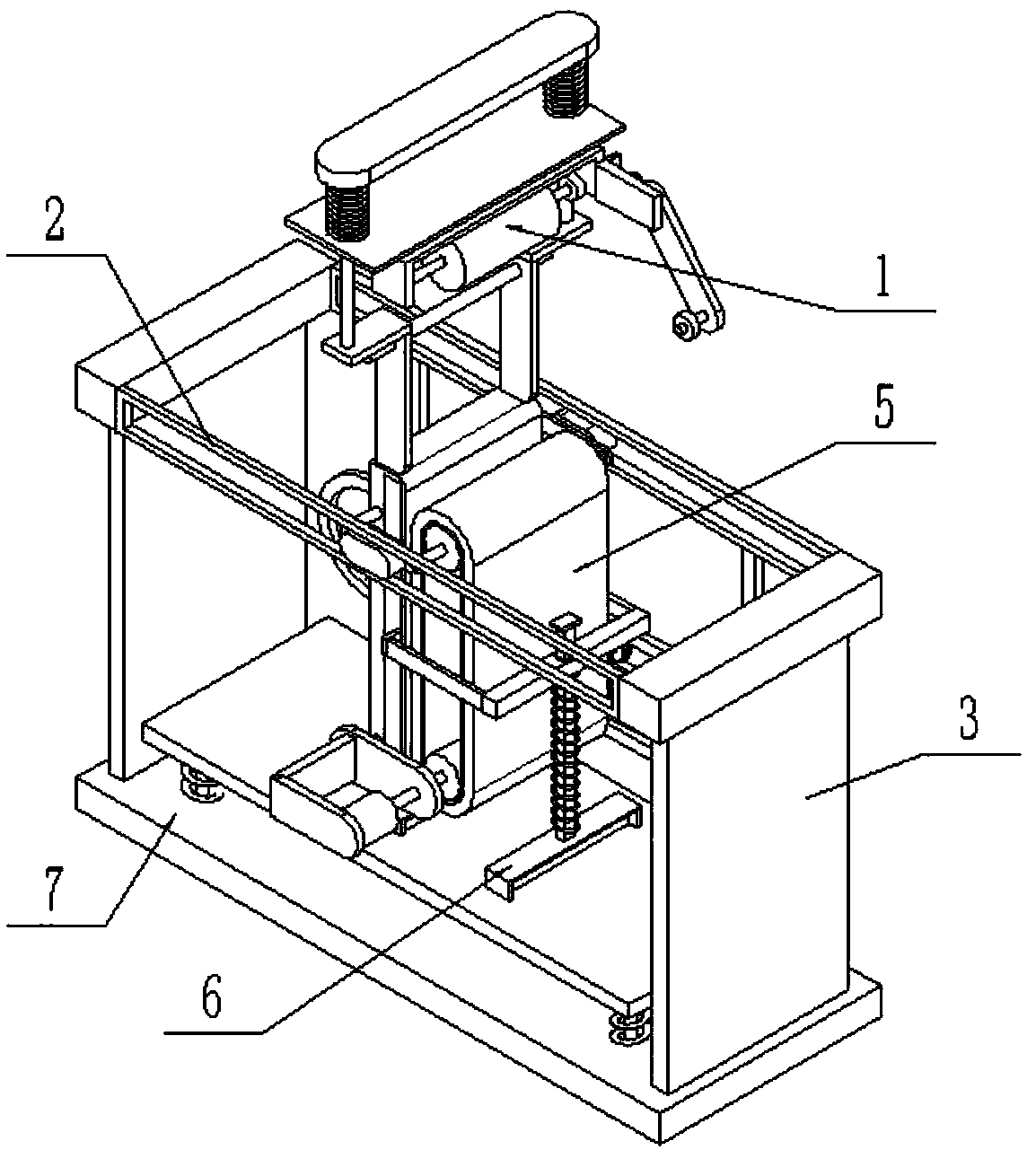
[0036] Such as Figure 1-16 As shown, an anti-loose roll cloth guiding and stacking device includes an anti-loosening cloth guiding assembly 1, an upper sliding frame assembly 2, a support plate 3, a lower sliding frame assembly 4, a cloth guiding mechanism 5, and a cloth press The flat mechanism 6 and the cloth laying platform assembly 7, the anti-loose cloth guide assembly 1 is connected to the upper end of the cloth guiding mechanism 5; the two sides of the bottom end of the upper sliding frame assembly 2 are respectively fixedly connected with a support plate 3, two The bottom end of the support plate 3 is fixedly connected to both sides of the top of the cloth laying platform assembly 7; the lower sliding frame assembly 4 is fixedly connected to the front side of the bottom end of the upper sliding frame assembly 2; the front side of the cloth guiding mechanism 5 The upper end of the sliding frame assembly is connected to the front end of the upper sliding frame assembly ...

specific Embodiment approach 2

[0040] Such as Figure 1-16 As shown, the upper sliding frame assembly 2 includes a left horizontal column 2-1, a right horizontal column 2-2, a front rectangular chute plate 2-3 and a rear rectangular chute plate 2-4; the left horizontal column 2- The front and rear ends of the right side of 1 are respectively fixedly connected to the front rectangular chute plate 2-3 and the rear rectangular chute plate 2-4; the front rectangular chute plate 2-3 and the rear rectangular chute plate 2-4 The right end is fixedly connected to the front and rear ends of the left side of the right cross column 2-2.

[0041] The lower sliding frame assembly 4 includes a rectangular support rod 4-1, an outer chute plate 4-2, an inner chute plate 4-3 and a connecting plate frame 4-4; the top end of the outer chute plate 4-2 is fixedly connected Two rectangular support bars 4-1, the upper ends of the two rectangular support bars 4-1 are fixedly connected to the lower end of the front rectangular chu...

specific Embodiment approach 3

[0042] Such as Figure 1-13As shown, the cloth guiding mechanism 5 includes a drive motor 5-1, a cloth guiding roller assembly 5-2, an auxiliary cloth pressing block assembly 5-3, a front sliding block 5-4, a rear sliding block 5-5, a front The connecting plate 5-6, the rear connecting plate 5-7 and the traction gear assembly 5-8; the upper end of the front side of the cloth guiding roller assembly 5-2 is rotationally fitted and connected to the left end of the front sliding block 5-4, and the cloth guiding The upper end of the rear side of the opening roller assembly 5-2 is rotatably connected to the left end of the rear sliding block 5-5, and the lower end of the front side of the cloth guide roller assembly 5-2 is rotatably connected to the left end of the front connecting plate 5-6. The lower end of the rear side of the cloth guide roller assembly 5-2 is rotatably connected to the left end of the rear connecting plate 5-7; -4 and the front connecting plate 5-6, the upper ...


PUM


Abstract

The invention relates to a roller cloth guide-unfolding device, in particular to an anti-loose roller cloth guide-unfolding stacking device. The anti-loose roller cloth guide-unfolding stacking devicecomprises an anti-loose cloth guide component, an upper sliding rack component, supporting plates, a lower sliding rack component, a cloth guide-unfolding mechanism, a cloth rolling flattening mechanism and a cloth laying platform component, the anti-loose cloth guide component is connected to the upper end of the cloth guide-unfolding mechanism, two sides of the bottom end of the upper sliding rack component are each fixedly connected with one of the supporting plates, the bottom ends of the two supporting plates are fixedly connected to two sides of the top end of the cloth laying platformcomponent, the lower sliding rack component is fixedly connected to the front side of the bottom end of the upper sliding rack component, the upper end of the front side of the cloth guide-unfolding mechanism is slidably connected to the front end of the upper sliding rack component in a matched manner, and the upper end of the rear side of the cloth guide-unfolding mechanism is slidably connectedto the rear end of the upper sliding rack component in a matched manner. By means of the anti-loose roller cloth guide-unfolding stacking device, cloth guide-unfolding, cloth conveying, cloth stacking and stacked cloth rolling and flattening can be synchronously realized, and the cloth guide-unfolding efficiency can be effectively improved.

Description

technical field [0001] The invention relates to a roll cloth guiding device, in particular to a roll cloth guiding and stacking device capable of preventing loosening. Background technique [0002] Most of the existing fabrics are stored in a roll-type storage, which can effectively save space and prevent the fabric from wrinkling. However, the roll-type fabric needs to be unfolded when it is processed and used. Due to the long length of the fabric, the current In the prior art, it is necessary to use the unwinding mechanism for unwinding processing, and after unwinding, it is necessary to perform layered laying processing, which is convenient for cutting and processing; but the structure of the existing unwinding mechanism is relatively simple, and only has a single Unwrapping function, but other processing on the unwrapped fabric cannot be done synchronously. Contents of the invention [0003] The purpose of the present invention is to provide a reel cloth guiding and s...

Claims


Application Information

Patent Timeline
Patent Type & Authority Applications(China)
IPC IPC(8): B65H20/02B65H45/10B65H45/30
CPCB65H20/02B65H45/10B65H45/30B65H2701/1133B65H2701/174
Inventor 张斌炜
Owner 南通格瑛纺织品有限公司
Why Eureka
Try Eureka