Embroidering device

An embroidery and conveying device technology, applied in the field of embroidery machinery, can solve the problems of heavy weight and limited materials to be wound, and achieve the effects of simple structure, smooth export and easy installation

Active Publication Date: 2018-06-19
田岛刺绣机械(中国)有限公司
View PDF12 Cites 1 Cited by
  • Summary
  • Abstract
  • Description
  • Claims
  • Application Information

AI Technical Summary

Problems solved by technology

Setting the retractable mechanism on the top can place large and heavy materials, which overcomes the problem of limited material placement in the prior art and the need to continuously replace materials; by setting a guide mechanism that guides the direction and position of the material It can avoid twisting and turning of ribbon-shaped or rope-like materials during embroidery, which will affect the embroidery quality, reduce the time for workers to sort out materials, and improve production efficiency; the discharge mechanism that fixes the embroidery position of materials can guide the ribbon-shaped materials that have been guided by the guide mechanism Or the rope-like material fixes the embroidery position, ensuring that the needle bar is accurately embroidered in the center of the ribbon-like material or rope-like material during the embroidery process, and the ribbon-like material or rope-like material is stably embroidered on the material

Method used


Image

  • Embroidering device
  • Embroidering device

Examples


Embodiment Construction

[0022] In order to enable those skilled in the art to better understand the technical solution of the present invention, the product of the present invention will be further described in detail below in conjunction with the embodiments and accompanying drawings.

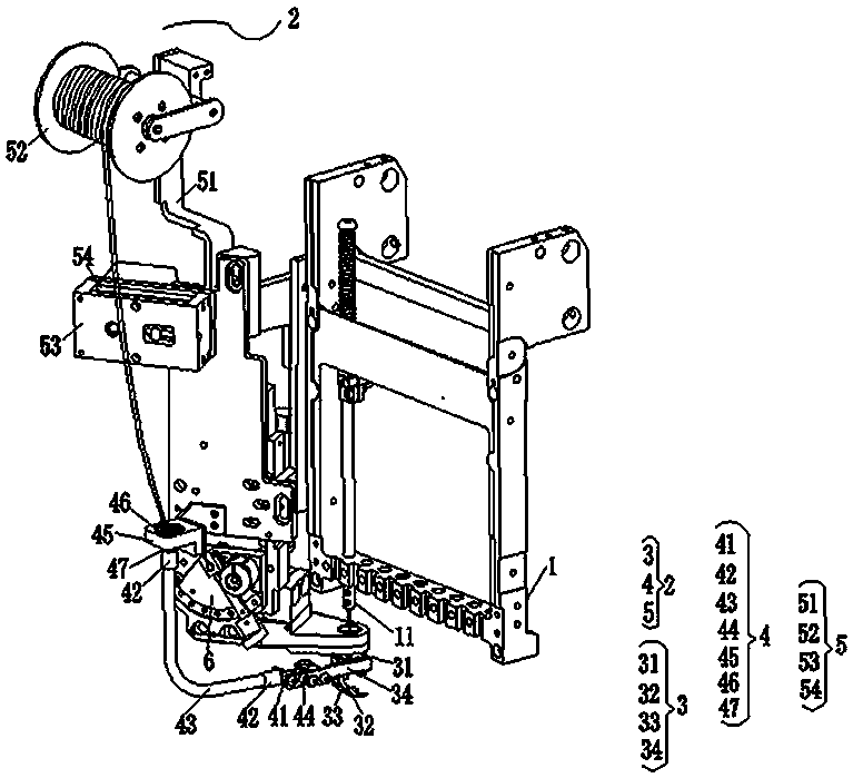
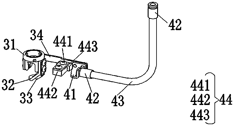
[0023] Such as figure 1 and figure 2 As shown, an embroidery device includes a needle bar box 1 arranged on the embroidery machine body, a material delivery device 2 matched with the needle bar box, a needle bar 11 is fixed inside the needle bar box, and the material delivery device 2 From bottom to top, there are discharging mechanism 3 for fixing the embroidery position of materials, guiding mechanism 4 for guiding the direction and position of materials, and retracting mechanism 5 for conveying materials in the direction of material conveying. Described discharge mechanism 3 comprises guide nozzle 31, guide nozzle 32 and material guide nozzle 33, and described guide nozzle 31 is arranged below needle bar 11, and...


PUM


Abstract

The invention discloses an embroidering device. The embroidering device comprises a needle bar box arranged on an embroidery machine body and a material delivering device matched with the needle bar box, wherein a needle bar is fixed in the needle bar box; the material delivering device is sequentially provided with a discharging mechanism for fixing a material embroidering position, a guiding mechanism for guiding the direction and the position of the material as well as a retracting mechanism which is positioned in the delivering direction of the material and is used for delivering the material from bottom to top. The embroidering device disclosed by the invention has the advantages of simple structure, easiness in mounting, reduced manual operation, improved production efficiency, smooth guiding of the material, low possibility of twisting or quilling, and the like.

Description

technical field [0001] The invention relates to the field of embroidery machinery, in particular to an embroidery device. Background technique [0002] With the continuous improvement of embroidery technology, more and more embroidery industry needs to increase the embroidery of various materials such as rope embroidery and belt embroidery on the basis of flat embroidery, so as to increase the value of embroidery. Currently on the market, rope embroidery and tape embroidery are generally embroidered by tape machines. Generally, under the head box of the tape machine, small material wheels are installed on both sides of the rotating shaft. The strip materials are wound on the material wheels. The wheel rotates with the rotating shaft, which can ensure that the position of the strip material remains unchanged, and the embroidery effect is stable. The distance between the tape embroidery machine head box and the needle plate is relatively large, which meets the installation con...

Claims


Application Information

Patent Timeline
Patent Type & Authority Applications(China)
IPC IPC(8): D05C7/08D05C13/00
CPCD05C7/08D05C13/00
Inventor 赵智健
Owner 田岛刺绣机械(中国)有限公司
Why Eureka
Try Eureka