Punching and drilling integrated type miner
An all-in-one, mining machine technology, applied in earth-moving drilling, slitting machinery, driving devices, etc., can solve the problems of high operation efficiency, low crushing efficiency, good coordination effect, etc., to achieve high operation efficiency, improve crushing efficiency, With good effect
- Summary
- Abstract
- Description
- Claims
- Application Information
AI Technical Summary
Problems solved by technology
Method used
Image

Examples
specific Embodiment approach 1
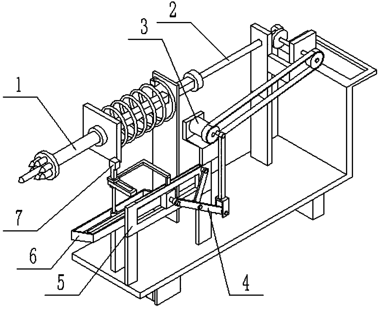
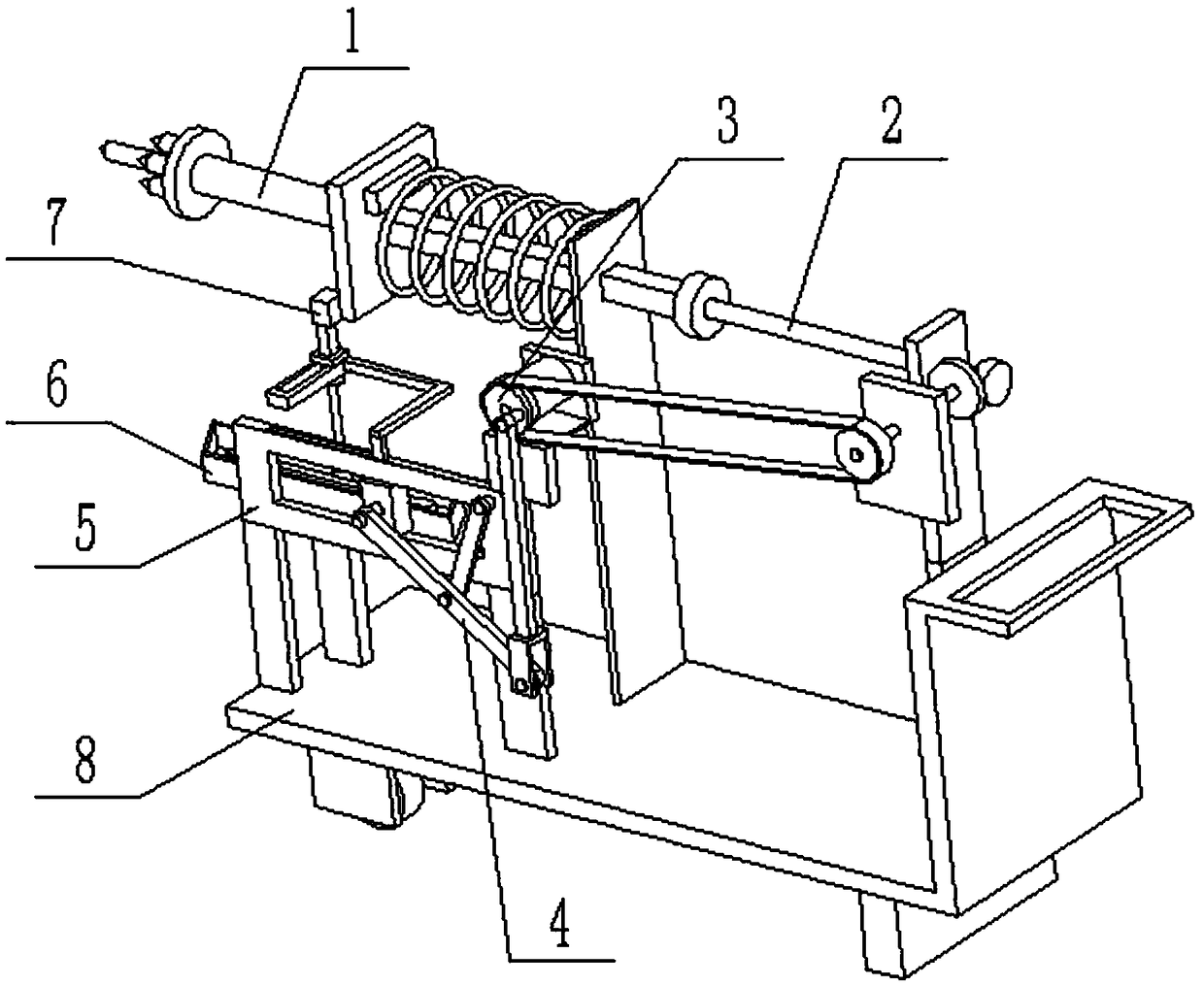
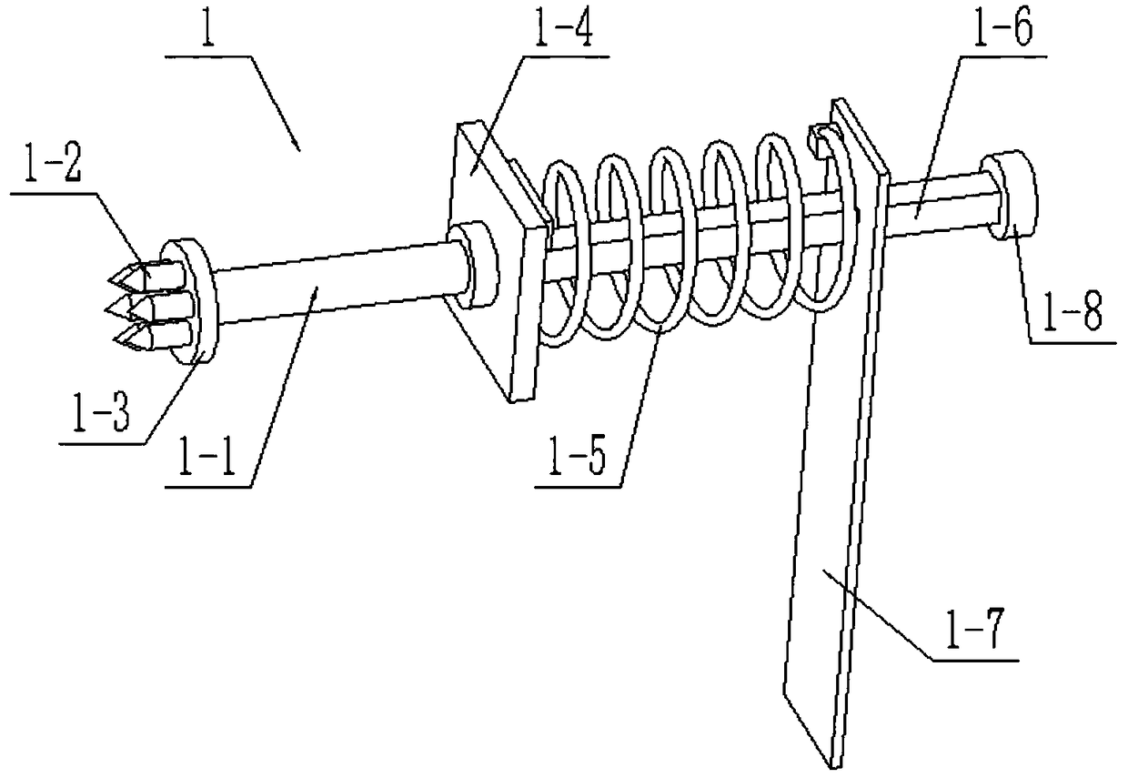
[0027] Such as Figure 1-11As shown, a punching and drilling integrated mining machine includes an impact rod assembly 1, a drill rod assembly 2, a drive assembly 3, a transmission rod assembly 4, a chute frame assembly 5, a chute seat assembly 6, and a sliding block frame assembly 7 And the base plate assembly 8, the drive assembly 3 is fixedly connected to the right side of the top of the chute frame assembly 5; the chute frame assembly 5 is fixedly connected to the top of the base plate assembly 8; the drive assembly 3 is connected to the drill rod assembly 2. The right end of the drill rod assembly 2 is fixedly connected to the top of the base plate assembly 8; the left end of the drill rod assembly 2 is rotatably connected to the inner side of the impact rod assembly 1; the drive assembly 3 is connected to the transmission rod assembly 4; The transmission rod assembly 4 is connected to the chute frame assembly 5, and the chute frame assembly 5 is connected to the sliding ...
specific Embodiment approach 2
[0028] Such as Figure 1-11 As shown, the driving assembly 3 includes a driving motor 3-1, a motor base 3-2, a transmission wheel 3-3 and an eccentric shaft 3-4; the front end of the output shaft of the driving motor 3-1 is fixedly connected to the transmission wheel Disc 3-3; the eccentric position of the front side of the transmission wheel 3-3 is fixedly connected to the eccentric shaft 3-4; the drive motor 3-1 is connected to the motor base 3-2 by screws; the transmission wheel 3-3 is connected to the drill pipe assembly 2 through a transmission chain; the eccentric shaft 3-4 is rotated and connected to the transmission rod assembly 4; the motor base 3-2 is connected to the chute frame assembly 5 by screws; the drive motor 3 -1 Connect the power supply and the control switch through wires. After the drive motor 3-1 is connected to the power supply and turned on by the control switch, the output shaft of the drive motor 3-1 drives the transmission wheel 3-3 to rotate, and ...
specific Embodiment approach 3
[0029] Such as Figure 1-11 As shown, the transmission rod assembly 4 includes a transmission connecting rod 4-1, a rotating connecting rod 4-2, a hinge connecting rod 4-3 and a hinge seat 4-4; one end of the transmission connecting rod 4-1 is rotatably connected On the eccentric shaft 3-4, the other end of the transmission link 4-1 is fixedly connected to the hinge seat 4-4; one end of the hinge link 4-3 is connected to the hinge seat 4-4 through a hinge shaft; the hinge The other end of connecting rod 4-3 is connected on the chute frame assembly 5 by hinge shaft; One end of described rotating connecting rod 4-2 rotates and is connected on the chute frame assembly 5, and the other end of rotating connecting rod 4-2 Hingedly connected at the middle end of hinged connecting rod 4-3. When the transmission rod assembly 4 is in use, the transmission connecting rod 4-1 moves under the drive of the eccentric shaft 3-4, and the transmission connecting rod 4-1 drives the hinge connec...
PUM
 Abstract
Description
Claims
Application Information
 - R&D
- Intellectual Property
- Life Sciences
- Materials
- Tech Scout
- Unparalleled Data Quality
- Higher Quality Content
- 60% Fewer Hallucinations
Browse by: Latest US Patents, China's latest patents, Technical Efficacy Thesaurus, Application Domain, Technology Topic, Popular Technical Reports.
© 2025 PatSnap. All rights reserved.Legal|Privacy policy|Modern Slavery Act Transparency Statement|Sitemap|About US| Contact US: help@patsnap.com