

Eight-unit L-shaped subarray application method and application device based on modularization
An application method and modular technology, applied in the manufacture of antenna array devices, electrical components, antenna arrays, etc., to achieve the effects of good fit, high degree of realization, and wide application range
- Summary
- Abstract
- Description
- Claims
- Application Information
AI Technical Summary
Problems solved by technology
Method used
Image

Examples
Embodiment 1
[0052] see Figure 4 , splicing square modules into a 12*20 antenna array by randomly selecting them from the module optional set. Each square module has a total of 8*8 antenna elements, so 15 modules are required. Calculate the far-field pattern of the array antenna to determine the antenna array layout scheme.
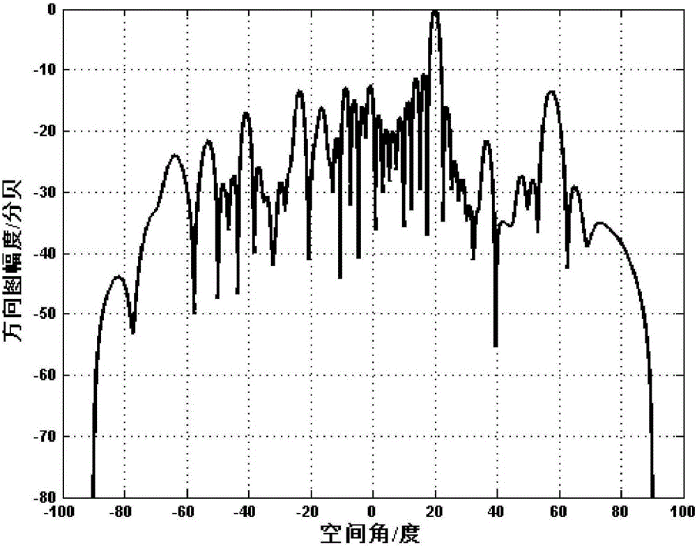
[0053] see Figure 5-6 , the figure is the direction diagram of the angle of view of the two main cut planes of the rectangular array, that is, the antenna array, under the condition of the antenna element spacing λ / 2 (half the working wavelength). Theoretically, the spacing between sub-arrays is approximately equal to 1.4 wavelengths, which is greater than the theoretical unit spacing where grating lobes cannot be detected by pattern scanning. Grating lobes will appear after pattern scanning, but no grating lobes can be seen in the calculation results, indicating that this scheme is feasible.
Embodiment 2
[0055] see Figure 7 , similar to Embodiment 1, a 16*16 antenna array is spliced by using square modules in the optional module set. Each square module has a total of 4*4 antenna elements, so 16 modules are required.
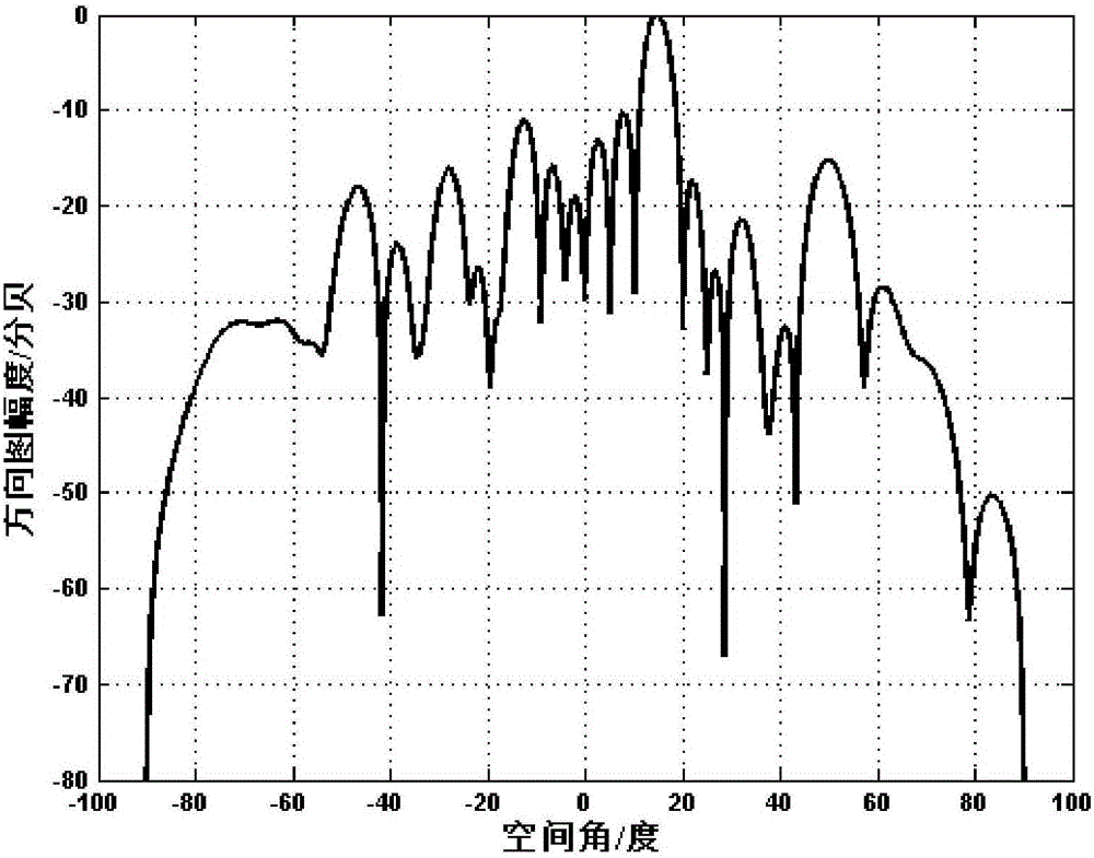
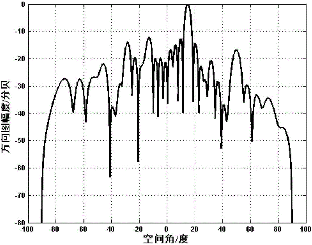
[0056] see Figure 8-9 , the figure is the direction diagram of the angle of view of the two main cut planes of the rectangular array, that is, the antenna array, under the condition of the antenna element spacing λ / 2 (half the working wavelength). Theoretically, the spacing between sub-arrays is approximately equal to 1.4 wavelengths, which is greater than the theoretical unit spacing where grating lobes cannot be detected by pattern scanning. Grating lobes will appear after pattern scanning, but no grating lobes can be seen in the calculation results, indicating that this scheme is feasible.
[0057] To sum up, the present invention proposes an application method based on modularized 8-unit L-shaped sub-arrays. By selecting 8 8-unit L-shaped sub-arrays, mo...
PUM
 Abstract
Description
Claims
Application Information