Airbag grout-block valve pipe assembly for conveniently perforating and slip casting construction

A drilling grouting and grouting technology, which is applied in the field of engineering grouting, can solve the problems of low grouting pressure, slow speed, bending rigidity and easy reverse bending of the grouting bowl, and discount of grouting effect, etc. Slurry speed and slurry pressure, filling effect of dense slurry, and effect of good slurry non-return performance

Pending Publication Date: 2018-06-19
KUNMING SURVEY DESIGN & RES INST OF CREEC
View PDF8 Cites 4 Cited by
  • Summary
  • Abstract
  • Description
  • Claims
  • Application Information

AI Technical Summary

Problems solved by technology

[0003] After years of engineering practice and demonstration, it is found that the sleeve valve pipe grouting method has the following problems: (1) During the grouting process, with the increase of the grout pressure at the front of the sleeve valve pipe, the PVC grout with low bending stiffness The bowl is easily bent in reverse, causing grout leakage, resulting in a decrease in the grouting pressure at the front of the sleeve valve pipe, incomplete grouting, and even scrapping of the grouting pipe; Sleeve valve pipe construction method must control the grouting pressure, the grouting pressure is small and the speed is slow, the grouting radius is reduced and the time is long, the fluidity of the grout is reduced or even solidified, and finally the pipe is blocked, which seriously reduces the construction efficiency; (3) Drilling The rod opening does not have a non-return function. After the grouting construction is completed, the grout will flow back, and the grouting effect will be greatly reduced.

Method used


Image

  • Airbag grout-block valve pipe assembly for conveniently perforating and slip casting construction
  • Airbag grout-block valve pipe assembly for conveniently perforating and slip casting construction
  • Airbag grout-block valve pipe assembly for conveniently perforating and slip casting construction

Examples


Embodiment Construction

[0022] Attached below Figure 1-5 , to further describe the embodiments of the present invention.

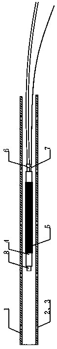
[0023] The present invention is an air bag grout stop valve pipe assembly that is convenient for drilling and grouting construction, such as figure 1 As shown, it includes a grouting drill pipe 1 and an airbag grouting valve tube body 4 . The body of the grouting drill pipe 1 is provided with a grouting hole 3 and a one-way grouting valve 2; the front end of the airbag grouting valve pipe body 4 is a grouting gun mouth 8, the pipe body is wrapped by a grouting airbag 5, and the tail is connected with a grouting Pipe 6 and air bag inflating pipe 7.

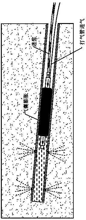
[0024] Before grouting, a sufficient amount of outside air is first pumped into the grout-stop air bag 5 through the air pump 7 to make it expand at high pressure to fill the gap between the drill pipe and the valve pipe body to achieve the function of efficiently plugging the grout, such as figure 2 shown.

[0025] The high-pre...


PUM


Abstract

The invention discloses an airbag grout-block valve pipe assembly for conveniently perforating and slip casting construction. The airbag grout-block valve pipe assembly includes a slip casting drill pipe, a rod body grout-block valve, a rod body grout-out hole, a slip casting valve pipe body, a grout-block airbag, a slip casting pipe, an inflating pipe and a slip casting gun; the slip casting drill pipe is provided with the rod body grout-out hole which is provided with the rod body grout-block valve, the slip casting drill pipe is provided with the slip casting pipe body which is provided with the grout-block airbag, and the grout-block airbag forms an integral whole on the slip casting valve pipe body; and the front portion of the slip casting valve pipe body is connecting with the slipcasting gun, the tail portion of the slip casting valve pipe body is connected with the slip casting pipe, and the grout-block airbag is connected with the inflating pipe. According to the airbag grout-block valve pipe assembly for the conveniently perforating and slip casting construction, the slip casting efficiency is greatly improved, compared with existing slip casting valve pipe products, the airbag grout-block valve pipe assembly has the advantages of higher grout-out speed and grout-out pressure, wider slip casting semi-diameter, denser grout liquid filling effect and better grout liquid non-return performance under the same slip casting pressure, and the phenomenon of pipe plugging due to use of the grout liquid with quick set and early strength can be effectively prevented.

Description

technical field [0001] The invention relates to the field of engineering grouting for tunnels and underground engineering, slope protection and treatment, foundation reinforcement, etc., and specifically relates to an air bag grouting stop valve pipe assembly that is convenient for drilling and grouting construction. Background technique [0002] Since the Soletancle-3 grouting method was invented in the 1950s, it has been widely used due to its advantages of controllable layered grouting and better control of grouting pressure and grouting range. Research and transformation have formed the current sleeve valve pipe grouting method. [0003] After years of engineering practice and demonstration, it is found that the sleeve valve pipe grouting method has the following problems: (1) During the grouting process, with the increase of the grout pressure at the front of the sleeve valve pipe, the PVC grout with low bending stiffness The bowl is easily bent in reverse, and grout l...

Claims


Application Information

Patent Timeline
Patent Type & Authority Applications(China)
IPC IPC(8): E21D11/10E02D15/02
CPCE21D11/105E02D15/02E02D2250/003
Inventor 孟小伟金国栋夏靖赵平杨陈相高如张椿民周锦强李光慧徐涛张细珠高骏陈歆孙庆洁董晓彪
Owner KUNMING SURVEY DESIGN & RES INST OF CREEC
Why Eureka
Try Eureka