Two-dimensional code positioning system based on 3D camera

A positioning system and camera technology, applied in measurement devices, instruments, surveying and navigation, etc., can solve problems such as large amount of calculation, lack of positioning, and inability to navigate, and achieve the effect of improving the success rate of positioning and improving the accuracy.

Inactive Publication Date: 2018-06-19
SHENZHEN QIANHAI YYD ROBOT CO LTD
View PDF7 Cites 6 Cited by
  • Summary
  • Abstract
  • Description
  • Claims
  • Application Information

AI Technical Summary

Problems solved by technology

[0005] RGB-D SLAM technology is currently slowly applied to robot positioning and navigation. Due to its relatively low cost and relatively easy deployment, it has become a future trend for service robot positioning and navigation. However, visual positioning and navigation technology is limited by current technologies. Development restrictions also have certain limitations. For example, it is greatly affected by the characteristics of the surrounding environment and light, and the calculation amount is relatively large. Real-time performance also requires the support of hardware computing capabilities.
In the application process, due to the influence of the environment, the robot that uses vision for positioning and navigation sometimes cannot locate its own position, resulting in the inability to navigate

Method used


Image

  • Two-dimensional code positioning system based on 3D camera

Examples


Embodiment Construction

[0023] In order to make the content of the present invention clearer and easier to understand, the content of the present invention will be described in detail below in conjunction with specific embodiments and accompanying drawings.

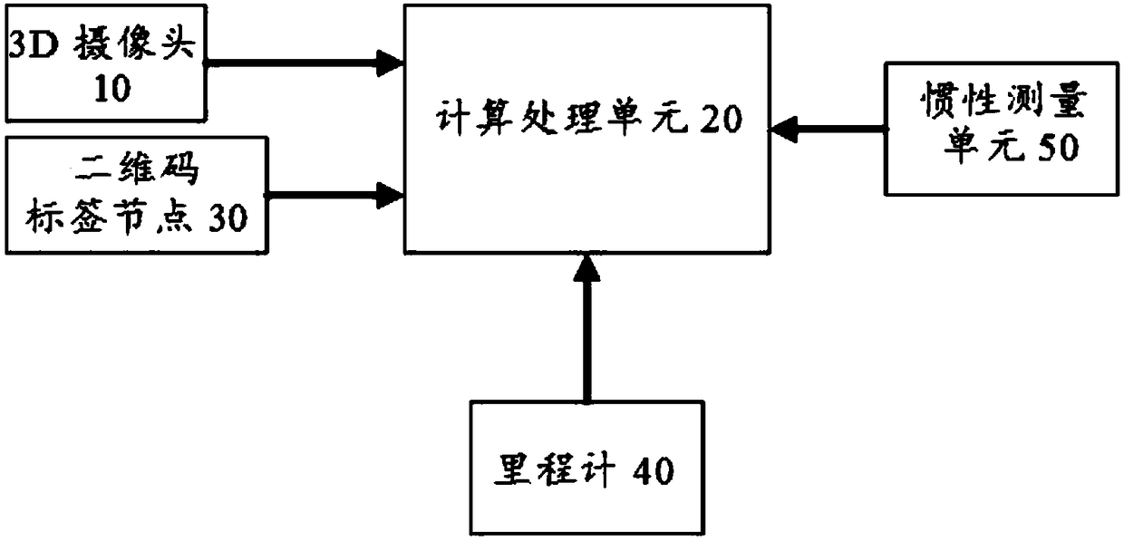
[0024] figure 1 A system block diagram of a two-dimensional code positioning system based on a 3D camera according to a preferred embodiment of the present invention is schematically shown.

[0025] like figure 1 As shown, the 3D camera-based two-dimensional code positioning system according to the preferred embodiment of the present invention includes: a 3D camera 10 , a calculation processing unit 20 and a plurality of two-dimensional code label nodes 30 .

[0026] The 3D camera 10 is loaded with a two-dimensional map generated through map construction, and each two-dimensional code label node 30 is arranged in the application environment of the two-dimensional code positioning system according to the two-dimensional map.

[0027] Moreover, ...


PUM


Abstract

The invention provides a two-dimensional code positioning system based on a 3D camera. The two-dimensional code positioning system comprises a 3D camera, a calculation processing unit and a pluralityof two-dimensional code label nodes; wherein the 3D camera is loaded with a two-dimensional map generated by map construction, two-dimensional code label nodes are arranged in application environmentof the two-dimensional code positioning system according to the two-dimensional map; moreover, the 3D camera is disposed on a target object; when the two-dimensional code positioning system performs two-dimensional code positioning operation, the 3D camera captures a picture of the two-dimensional code label nodes, and obtains a distance value relative to the two-dimensional code label nodes according to the picture, the calculation processing unit uses the distance value to calculate position coordinates of a robot relative to the two-dimensional code label nodes, and the calculated positioncoordinates are converted into a map coordinate system.

Description

technical field [0001] The invention relates to a two-dimensional code positioning system based on a 3D camera. Background technique [0002] At present, with the development of mobile robot technology, more and more mobile robot products have entered the consumer market and commercial market. In the commercial market, mobile robots are mainly used for guidance, shopping guide, explanation, introduction, welcome, and item delivery. As a mobile platform, mobile robot has mobility as its basic function. The positioning function of mobile robots is one of the key technologies for mobile robots to achieve autonomy. Only when a mobile robot understands its position in the current environment can it decide where to go next? and how to get to the destination? There are many current positioning methods for mobile robots, such as: WIFI positioning, RFID positioning, UWB positioning, visual positioning, iBeacon positioning, wireless sensor positioning, laser positioning and ultraso...

Claims


Application Information

Patent Timeline
Patent Type & Authority Applications(China)
IPC IPC(8): G01C21/20G01C21/16
CPCG01C21/165G01C21/20
Inventor 李明明
Owner SHENZHEN QIANHAI YYD ROBOT CO LTD
Why Eureka
Try Eureka