Centrifugal adsorption filter device for cooling liquid

A technology of filtering device and coolant, applied in solid separation, magnetic separation, maintenance and safety accessories, etc., can solve the problems of tool head wear, residue on the tool head or cutting metal surface, uneven cutting surface, etc. Efficiency, protecting the cutting process, increasing the speed of cleaning

Inactive Publication Date: 2018-06-22
袁加衡
View PDF4 Cites 14 Cited by
  • Summary
  • Abstract
  • Description
  • Claims
  • Application Information

AI Technical Summary

Problems solved by technology

[0002] Coolant is often used in the process of CNC lathe processing. The main function of the coolant is: when the tool of the lathe mills the raw material, it is sprayed on the working contact between the tool and the metal surface to cool down and lubricate the tool head. , to prevent the tool head from overheating and breaking, a large amount of metal debris will be generated during the cutting process, and these metal debris will fall into the coolant circulation box together with the coolant. Generally, the coolant enters the circulation box and will be filtered Generally, multi-layer mesh plates are used to filter metal debris, but there are still many metal fine particle impurities that cannot be fully filtered out. When these metal impurities are sprayed on the cutter head again through the circulating water pump, the metal impurities may remain. On the tool head or cutting metal surface, it may cause unevenness of the cutting surface or serious wear of the tool head

Method used


Image

  • Centrifugal adsorption filter device for cooling liquid
  • Centrifugal adsorption filter device for cooling liquid
  • Centrifugal adsorption filter device for cooling liquid

Examples


Embodiment Construction

[0018] The following will clearly and completely describe the technical solutions in the embodiments of the present invention with reference to the accompanying drawings in the embodiments of the present invention. Obviously, the described embodiments are only some, not all, embodiments of the present invention. Based on the embodiments of the present invention, all other embodiments obtained by persons of ordinary skill in the art without making creative efforts belong to the protection scope of the present invention.

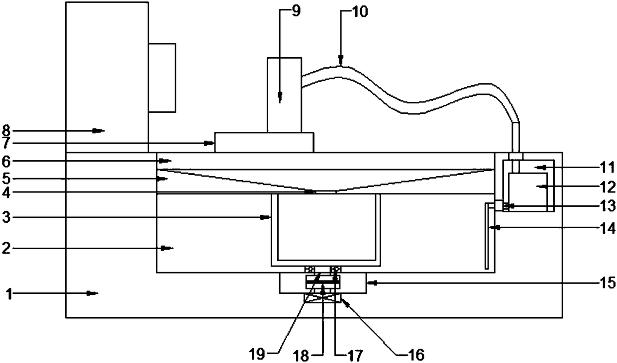
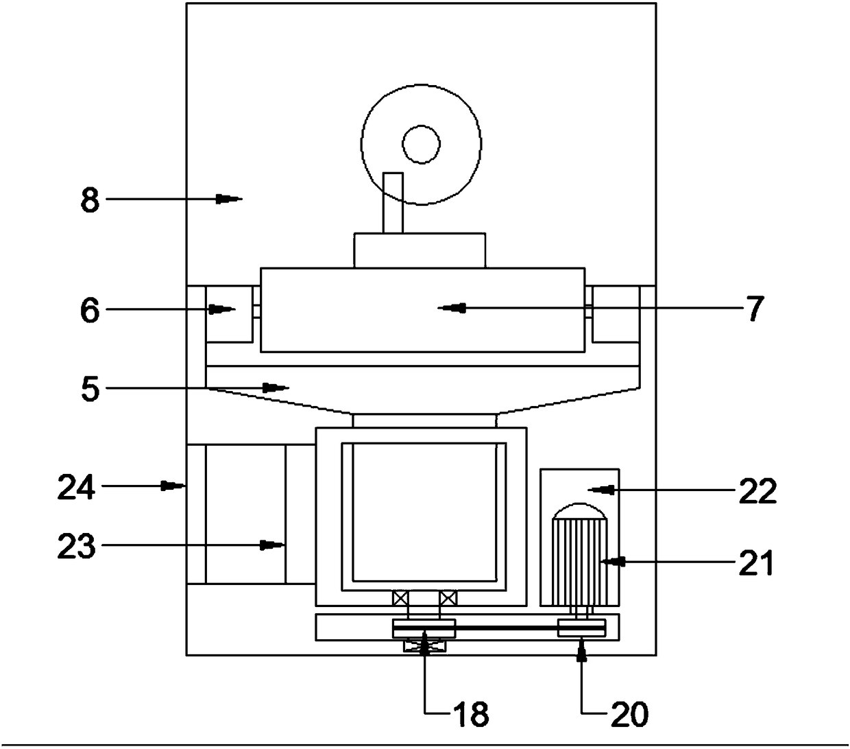
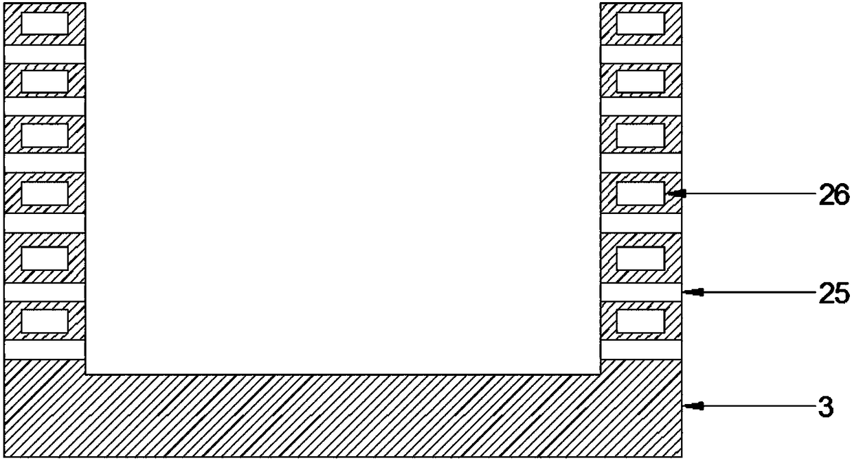
[0019] see Figure 1~3 , in an embodiment of the present invention, a filter device for centrifugal adsorption of coolant, comprising a lathe base 1, a filter box 2, an adsorption drum 3, a filter screen 4, a liquid leakage slope 5, a travel track 6, a track seat 7, and a lathe drive box 8. Tool holder 9, liquid delivery pipe 10, water pump chamber 11, water pump 12, water plug 13, water pipe 14, connection chamber 15, support bearing 16, support plug 17, driv...


PUM


Abstract

The invention discloses a centrifugal adsorption filter device for cooling liquid. The centrifugal adsorption filter device comprises a lathe base; the lathe base is internally provided with a filterbox, a water pump cavity, a connection cavity, and a motor cavity; and a liquid leakage slope is arranged below a rail seat, a filter screen is arranged at the bottom of the liquid leakage slope, thecenter position of the filter box is provided with an adsorption roller, the side wall of the adsorption roller is provided with water leakage holes and magnets, the bottom of the adsorption roller isfixedly provided with a rotating rod, a driving pulley of the rotating rod is connected with a motor pulley of a driving motor through a belt, the front side of the filter box is provided with a maintenance access and a water blocking plate, the bottom end of a water pumping pipe extends into the bottom of the filter box, the water pumping pipe is connected with the water pumping end of a water pump through a water blocking plug, the water pump is arranged on the inner bottom surface of a water pump cavity, the water draining end of the water pump is connected to a liquid supply pipe, and thetop end of the liquid supply pipe is fixed on a tool holder. The adsorption roller with the built-in magnets is used for greatly improving the adsorption efficiency of metal impurity inside the cooling liquid.

Description

technical field [0001] The invention relates to the field of filter devices, in particular to a filter device for centrifugal adsorption of cooling liquid. Background technique [0002] Coolant is often used in the process of CNC lathe processing. The main function of the coolant is: when the tool of the lathe mills the raw material, it is sprayed on the working contact between the tool and the metal surface to cool down and lubricate the tool head. , to prevent the tool head from overheating and breaking, a large amount of metal debris will be generated during the cutting process, and these metal debris will fall into the coolant circulation box together with the coolant. Generally, the coolant enters the circulation box and will be filtered Generally, multi-layer mesh plates are used to filter metal debris, but there are still many metal fine particle impurities that cannot be fully filtered out. When these metal impurities are sprayed on the cutter head again through the ...

Claims


Application Information

Patent Timeline
Patent Type & Authority Applications(China)
IPC IPC(8): B23Q11/10B03C1/10
CPCB03C1/10B23Q11/1069
Inventor 袁加衡
Owner 袁加衡
Why Eureka
Try Eureka