
A Bionic Load Mobility Exoskeleton System

An exoskeleton and motorized technology, applied in manipulators, program-controlled manipulators, manufacturing tools, etc., can solve the problems of uncoordinated man-machine movement, ineffective power assist, poor wearing comfort, etc., and achieve low structural complexity and flexible driving methods , Improve the effect of wearing comfort

Active Publication Date: 2020-04-10
NAT UNIV OF DEFENSE TECH
View PDF9 Cites 0 Cited by
  • Summary
  • Abstract
  • Description
  • Claims
  • Application Information

AI Technical Summary

Problems solved by technology

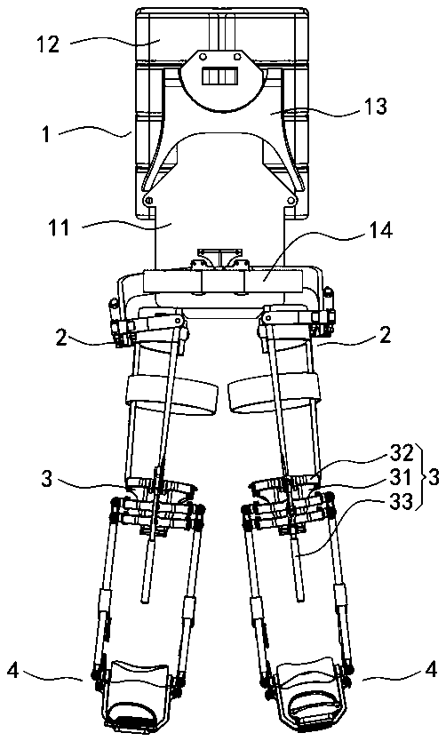
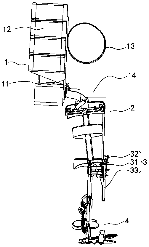
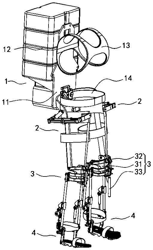
[0004] The technical problem to be solved by the present invention is to provide a load-driven exoskeleton system for the existing exoskeleton robots that have uncoordinated human-machine movements, internal friction, poor wearing comfort, and ineffective power-assisted effects. The rotation center of the joint coincides with the joint center of the human body, avoiding the space interference between the exoskeleton suit and the human body, reducing internal friction, more comfortable to wear, more coordinated with the human body movement, and more reasonable energy supply, so as to truly enhance the mobility of the human body.

Method used


Image

  • A Bionic Load Mobility Exoskeleton System
  • A Bionic Load Mobility Exoskeleton System
  • A Bionic Load Mobility Exoskeleton System

Examples


Embodiment 2

[0057] This embodiment is basically the same as the first embodiment, and the main difference is that the driving element and the driving system are different. Such as Figure 13 As shown, in this embodiment, the first drive element 25, the second drive element 33, and the third drive element 45 are actuators composed of linear servo motors, and the actuators are provided with stroke detection sensors 50; There is a two-stage drive unit 5, and the two-stage drive unit 5 includes a control module 51 and an instantaneous high-power circuit and a long-term low-power circuit corresponding to each actuator, and all instantaneous high-power circuits share one instantaneous high-power source HS, and all long-term The long-time low-power circuit shares a long-time low-power source LS, and the control terminal of the control switch Swi and the output terminal of the travel detection sensor 50 are respectively connected to the control module 51 . Similarly, the long-term low-power sour...

Embodiment 3

[0059] This embodiment is basically the same as the second embodiment, and the main difference is that the form of the dual-stage drive unit 5 is different. In this embodiment, a separate instantaneous high-power source HS is provided on the instantaneous high-power circuit, and a separate long-term low-power source LS is arranged in series on the long-term low-power circuit. Let me repeat.


PUM


Abstract

The invention discloses a bionic load maneuvering exoskeleton system. The system comprises an axis L21 of two first rotating shafts at the two ends of a hip baffle plate, an axis L22 of a third rotating shaft of a hip bearing component, a central axis L23 of a parallel connecting rod mechanism, a central point O1 of a hip joint intersects with the inner side of the opening of the hip baffle plate,a center line L41 of a parallelogram structure, a rotation center line L42 of a shoe pad, a hinge point center connecting line L43 of an ankle joint support and two small leg force bearing rods and an ankle joint center point O2, wherein the center line L41 of the parallelogram structure, the rotation center line L42 of the shoe pad and the hinge point center connecting line L43 of the ankle joint support and the two small leg force bearing rods intersect with the ankle joint center point O2 at the opening end of the ankle joint support; and the rotating center of each joint coincides with the center of the joint of the human body, the geometric interference between the exoskeleton clothes and the human body can be avoided in the space, the internal consumption of the exoskeleton clothesand the human body movement can be reduced, the wearing comfort of the exoskeleton suit is improved, the structure is low in complexity, the energy consumption is low, the reliability is good, and thedriving mode is flexible.

Description

technical field [0001] The invention relates to an exoskeleton robot, in particular to a bionic load motorized exoskeleton system, which is worn by a human body and has the function of enhancing the wearer's load capacity and maneuverability. Background technique [0002] Foreign research on exoskeleton has a certain basis and results, and domestic research on it is also on the rise. At present, exoskeletons are mainly used in medical rehabilitation, industrial production, individual combat and other fields. Existing exoskeleton robots simplify the human body structure in terms of bionic design, especially the simplification of the joints and their motions, which makes the exoskeleton and human motion different, and the wearing comfort is not good. On the other hand, there are not many domestic studies on load-bearing exoskeletons that enhance human body functions, and there is a big gap between the research on modern individual comprehensive weaponry and developed countrie...

Claims


Application Information

Patent Timeline
Patent Type & Authority Patents(China)
IPC IPC(8): B25J9/00
CPCB25J9/00B25J9/0006
Inventor 尚建忠罗自荣吴国恒陈芳罗佳俊李欣陈杨
Owner NAT UNIV OF DEFENSE TECH
Learn More