
A system and method for ultrasonic vibration-assisted gear shaping processing of cylindrical gears

An ultrasonic vibration and gear technology, applied in the field of gear processing, can solve problems such as circulation, and achieve the effects of reducing lateral vibration, lowering temperature, and improving cutting efficiency

Active Publication Date: 2020-04-24
CENT SOUTH UNIV
View PDF5 Cites 0 Cited by
  • Summary
  • Abstract
  • Description
  • Claims
  • Application Information

AI Technical Summary

Problems solved by technology

For this reason, the existing technology often uses ultrasonic vibration to assist gear processing, so that the cutting force in the processing process is smaller, the tool wear is lower, the surface quality of the workpiece is better, and the cutting efficiency is higher. The existing research on gear shaping processing It is mainly focused on one-dimensional ultrasonic longitudinal vibration assisted gear shaping machining, but due to the height of the gear shaping cutter, it is difficult to achieve a complete non-contact cycle between the tool and the workpiece within one ultrasonic cycle
In the two-dimensional ultrasonic vibration-assisted vibration machining in the axial and horizontal directions, the original motion should be as follows: Image 6 As shown, but due to factors such as the amplitude of ultrasonic vibration, bending deformation caused by ultrasonic vibration, and bending deformation caused by cutting force in gear shaping processing, it will be as follows Figure 7 The geometric interference shown

Method used


Image

  • A system and method for ultrasonic vibration-assisted gear shaping processing of cylindrical gears
  • A system and method for ultrasonic vibration-assisted gear shaping processing of cylindrical gears
  • A system and method for ultrasonic vibration-assisted gear shaping processing of cylindrical gears

Examples


Embodiment Construction

[0027] The present invention will be described in detail below in conjunction with the accompanying drawings and embodiments.

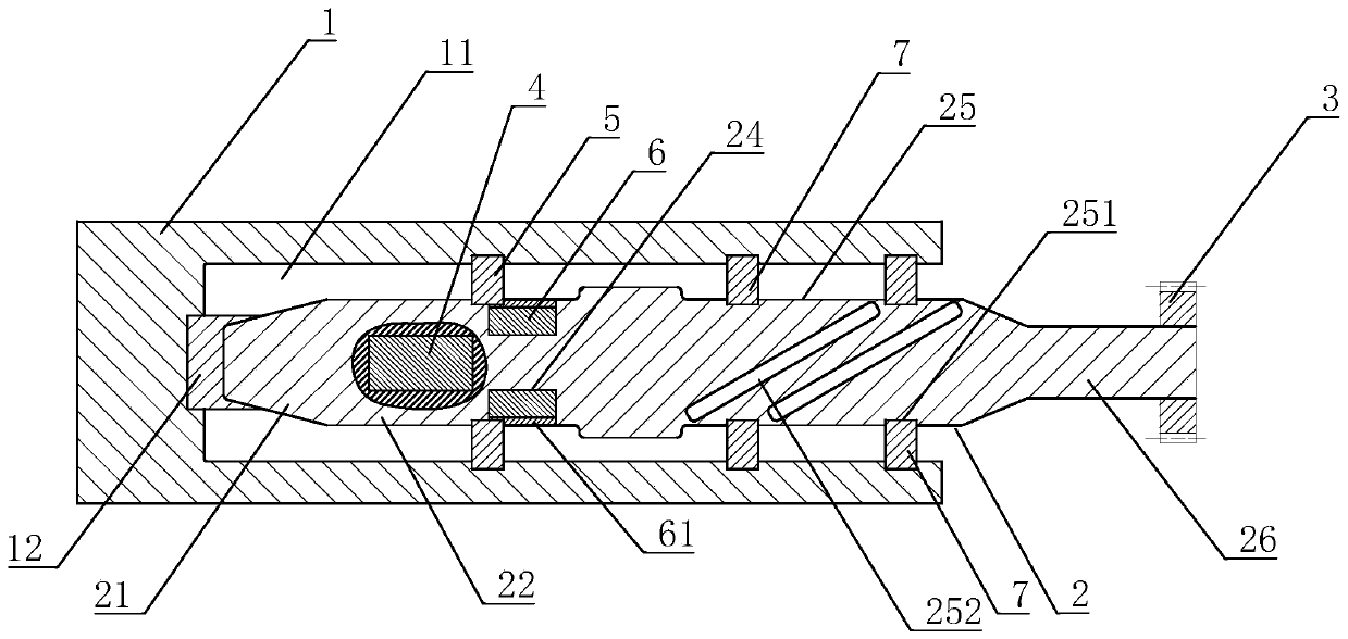
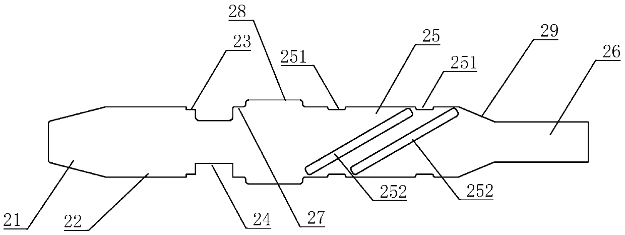
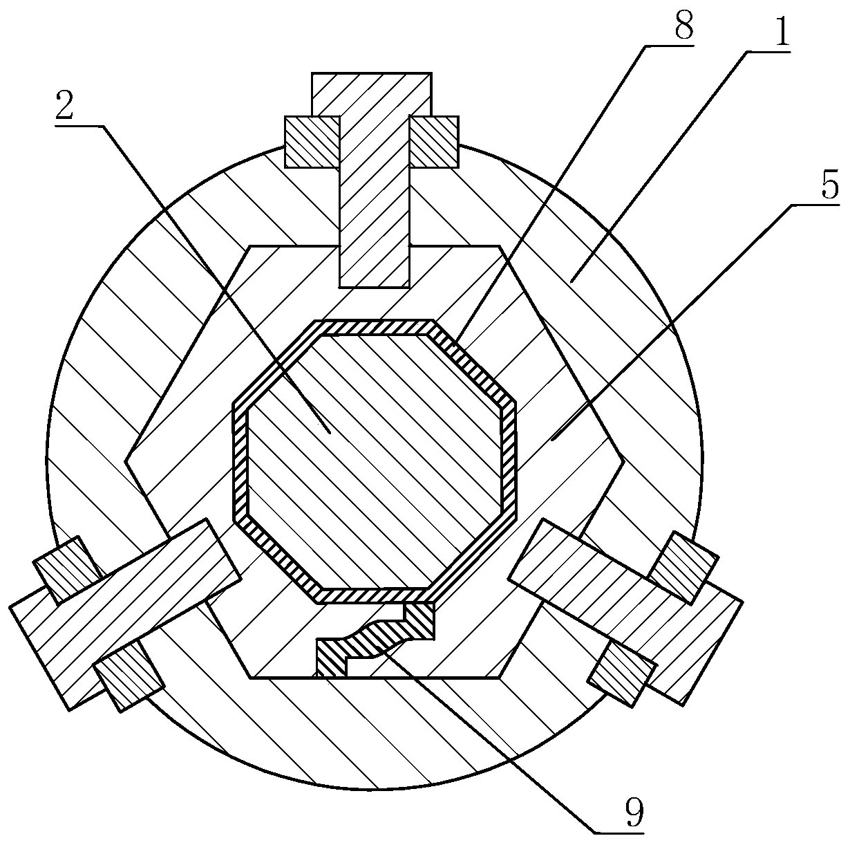
[0028] refer to Figure 1 to Figure 8 , a system for ultrasonic vibration-assisted gear shaping processing of cylindrical gears according to the present invention includes a first connecting piece 1 and a vibration horn 2 . The material of the first connecting piece 1 is high manganese steel, and its outer ring is a regular hexahedron or cylinder. The first connecting piece 1 is connected to the tool table of the machine tool. The shape and connection method of the outer ring vary with the tool table of the machine tool. , the feed and movement of the tool table of the machine tool drives the tool gear 3 on the vibrating horn 2 to process the workpiece. The first connecting member 1 is provided with an inner chamber 11 extending along the axis of its outer circle. The vibration horn 2 is inserted into the inner cavity 11 , and its axis coincides wit...


PUM


Abstract

The invention discloses a system for machining a cylindrical gear through ultrasonic vibration assisted gear shaping. The system comprises a first connecting part and a vibrating amplitude variation rod; the first connecting part is provided with an inner cavity with a polygonal section; the vibration amplitude variation rod is inserted into the inner cavity, and the vibration amplitude variationrod comprises a matched positioning section, a first actuator installation section, a second connecting part installation section, a second actuator installation section, a third connecting part installation section and a cutter gear installation section which are sequentially arranged. By means of the system and a method using the system, various axial, bending and torsion coupling vibration canbe achieved, the material cutting efficiency is improved, the service life of a cutter is prolonged, the surface quality of workpieces is improved, and rough machining and fine machining of the gear are synchronously achieved. Besides, ultrasonic vibration generates the ultrasonic cavitation effect so that a cutting fluid can permeate into the contact position more deeply, the temperature of the contact area between the workpieces and the cutter is further reduced, the surface quality of the workpieces is improved, and the service life of the cutter is prolonged.

Description

technical field [0001] The invention relates to the field of gear processing, in particular to a system and method for ultrasonic vibration-assisted gear shaping processing of cylindrical gears. Background technique [0002] At present, in cylindrical gears, due to the different tooth shapes, cylindrical gears are divided into spur gears, helical gears, bolt gears and hyperbolic gears. The tooth shapes are straight line, oblique line, spiral curve, hyperbolic, The relative motion of tool and workpiece is one-dimensional and two-dimensional. Gear shaping is an effective method for processing gears, such as Figure 5 As shown, during the gear shaping process, the tool gear A feeds up and down to process the workpiece gear B. The gear after the gear shaping process usually requires finishing processes such as grinding, lapping, or honing to improve its surface quality and meet complex working conditions. usage requirements. For this reason, the existing technology often uses ...

Claims


Application Information

Patent Timeline
Patent Type & Authority Patents(China)
IPC IPC(8): B06B1/06B23F5/12B23F23/00
CPCB06B1/0607B23F5/12B23F23/00
Inventor 唐进元陈雪林丁撼
Owner CENT SOUTH UNIV
Learn More