Potential energy recycling and motor speed regulation double pump hydraulic energy saving system

A technology of motor speed regulation and potential energy recovery, which is applied to fluid pressure actuation system components, mechanical equipment, fluid pressure actuation devices, etc., can solve the problems of insufficient energy recovery, improved recovery efficiency, unfavorable machinery, etc., and achieve compact structure , Improve recovery efficiency and reduce working volume

Pending Publication Date: 2018-06-22
FUJIAN UNIV OF TECH
View PDF11 Cites 4 Cited by
  • Summary
  • Abstract
  • Description
  • Claims
  • Application Information

AI Technical Summary

Problems solved by technology

When the potential energy of the above scheme is recovered, the accumulator hydraulic cylinder goes down, and all the oil in the large cavity must be charged into the accumulator, so that the minimum working volume of the accumulator must be greater than the maximum volume of the hydraulic cylinder large cavity, which is not conducive to Space-compact mobile machinery, etc.
Moreover, the above scheme only adopts hydraulic recovery, and its recovery energy is not sufficient or the recovery efficien

Method used


Image

  • Potential energy recycling and motor speed regulation double pump hydraulic energy saving system

Examples


Embodiment Construction

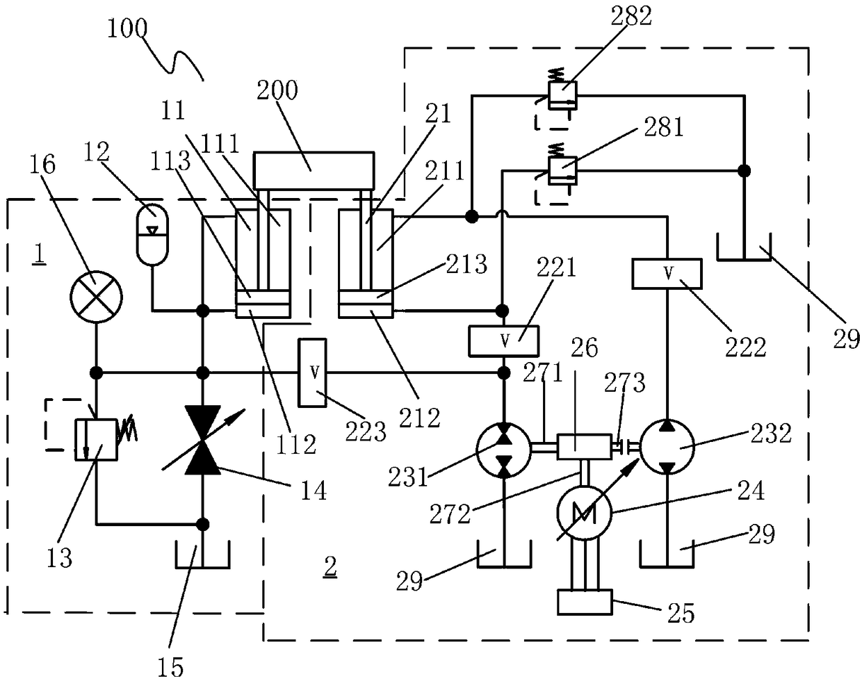
[0020] see figure 1 As shown, the double-pump hydraulic energy-saving system 100 of potential energy recovery and motor speed regulation of the present invention includes an energy recovery system 1 and a volumetric speed regulation control system 2;

[0021] The energy recovery system 1 includes an energy storage hydraulic cylinder 11 and an accumulator 12, a first safety valve 13, a shut-off valve 14, and an oil tank 15, and a pressure gauge 16; the energy storage hydraulic cylinder 11 can be a single-rod double-acting The hydraulic cylinder has an upper oil chamber 111 and a lower oil chamber 112 separated by a first piston 113, and the hydraulic effective area of ​​the upper oil chamber 111 is smaller than the hydraulic effective area of ​​the lower oil chamber 112, the upper oil chamber 111 and the lower oil chamber 112 The lower oil chamber 112 is connected to the accumulator 12; the upper oil chamber 111 and the lower oil chamber 112 are respectively connected to the fu...


PUM


Abstract

The invention provides a potential energy recycling and motor speed regulation double pump hydraulic energy saving system. The potential energy recycling and motor speed regulation double pump hydraulic energy saving system comprises an energy recycling system and a volume speed regulation control system. The energy recycling system comprises an energy accumulation hydraulic cylinder and an energyaccumulator. The energy accumulation hydraulic cylinder is provided with an upper oil cavity and a lower oil cavity which are connected with the energy accumulator. The hydraulic effective area of the upper oil cavity is smaller than that of the lower oil cavity. The volume speed regulation control system comprises a main hydraulic cylinder, a first switch valve, a second switch valve, a first hydraulic pump motor all-in-one machine, a second hydraulic pump motor all-in-one machine, a generator motor all-in-one machine and a frequency converter. The main hydraulic cylinder is provided with anupper liquid cavity and a lower liquid cavity. The e hydraulic effective area of the upper liquid cavity is smaller than that of the lower liquid cavity. The lower liquid cavity, the first switch valve, the first hydraulic pump motor all-in-one machine, the generator motor all-in-one machine and the frequency converter are sequentially connected. The upper liquid cavity, the second switch valve,the second hydraulic pump motor all-in-one machine, the generator motor all-in-one machine and the frequency converter are sequentially connected. Electric recycling and hydraulic energy recycling arecombined, the energy recycling efficiency is improved, and the system speed control performance is improved.

Description

technical field [0001] The invention relates to an energy recovery and control system, in particular to a potential energy recovery and control system for engineering equipment. Background technique [0002] In many construction machines, a large amount of potential energy is wasted during lowering. For example, during the working process of a hydraulic excavator, the boom swings up and down frequently, and the working device of the hydraulic excavator is heavy and has a large inertia. Valve throttling to adjust speed, but when decelerating and braking, most of the potential energy of the working device is converted into heat energy at the main valve throttling port, which not only causes energy waste, but also leads to an increase in system temperature and a reduction in the life of hydraulic components . [0003] At present, the research on energy recovery is mainly concentrated in the field of automobiles, but the research on energy recovery in the field of construction...

Claims


Application Information

Patent Timeline
IPC IPC(8): F15B11/16F15B11/17F15B13/02F15B1/04F15B21/04
CPCF15B1/04F15B11/16F15B11/17F15B13/02F15B21/042Y02E60/16
Inventor 张树忠唐一文晏岱黄豪杰练国富
Owner FUJIAN UNIV OF TECH
Why Eureka
Try Eureka