Eureka AIR delivers breakthrough ideas for toughest innovation challenges, trusted by R&D personnel around the world.

Self-adaptive control fuel gas spray-blowing device and method based on charge level video recognition

A technology of self-adaptive control and injection device, applied in the field of sintering, can solve problems such as excessive ignition, negative impact on stable production of gas injection device, and poor air permeability.

Active Publication Date: 2018-06-22
ZHONGYE-CHANGTIAN INT ENG CO LTD
View PDF19 Cites 5 Cited by
  • Summary
  • Abstract
  • Description
  • Claims
  • Application Information

AI Technical Summary

Problems solved by technology

[0006] At present, in the production and application of the gas injection device, due to the influence of various factors such as moisture, pressing material, trolley furnace bar, etc., the material surface of the sintering machine entering the injection hood is prone to whitening in some areas of the material surface
The reason for this abnormal working condition is that due to the influence of many factors on the local area of ​​the material surface, the degree of ignition is too high, which not only ignites the solid carbon particles in the material layer, but also part of the iron in the iron ore powder has been melted and reduced, resulting in the The surface of the material in the area forms an over-melted layer, and the air permeability is seriously deteriorated
[0007] At present, for the working condition that the abnormal ignition causes the local air permeability of the material surface to deteriorate, the existing technology does not have any treatment means, and the operator can only observe the material surface on the spot, artificially judge and lower the main pipe valve of the gas injection device as a whole There are the following disadvantages in doing so:
If the range is too large, the overall gas injection volume will be reduced too much, which will have a serious negative impact on the gas injection-assisted sintering effect over time;
[0009] 2. The labor intensity of the operator is too high: Due to the lack of means and devices for automatic monitoring of the material level, the operator has to go to the material level monitoring platform to monitor the material level on a regular or irregular basis while handling other busy tasks
This not only increases the labor intensity of the operator, but also because the operator's monitoring is not continuous, many unhealthy (over-melted) material surfaces have not been detected, which has also brought serious negative effects on the stable production of the gas injection device. influences

Method used


Image

  • Self-adaptive control fuel gas spray-blowing device and method based on charge level video recognition
  • Self-adaptive control fuel gas spray-blowing device and method based on charge level video recognition
  • Self-adaptive control fuel gas spray-blowing device and method based on charge level video recognition

Examples


Embodiment 1

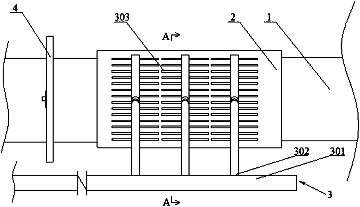
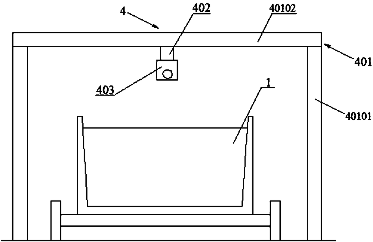
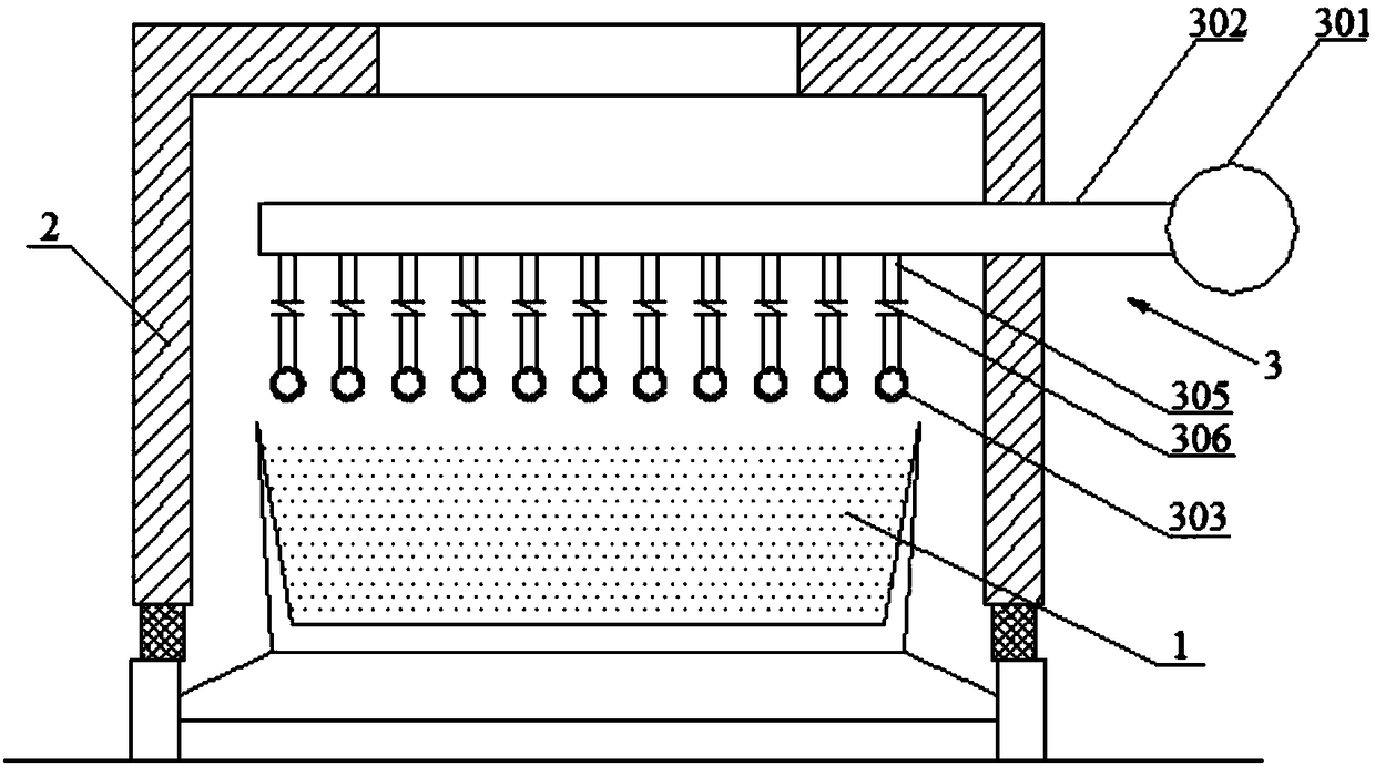
[0080] Such as figure 1 As shown, an adaptive control gas injection device based on material level video recognition, the device includes a sintering machine trolley 1, an injection cover 2, and a gas injection device 3. The gas injection device 3 includes a gas injection main pipe 301 , a gas injection branch pipe 302 and a gas injection pipe 303 . The blowing hood 2 is located on the upper part of the sintering machine trolley 1 . The gas injection main pipe 301 is arranged on the outside of the injection cover 2 . The gas injection pipe 303 is arranged above the sintering machine trolley 1 , and the gas injection pipe 303 is located in the injection hood 2 . One end of the gas injection branch pipe 302 is connected to the gas injection main pipe 301 and the other end is connected to the gas injection pipe 303 . The gas injection pipe 303 is provided with a gas injection hole 304 . The device also includes a material level video recognition device 4 arranged upstream of ...

Embodiment 2

[0086] Such as Figure 5 As shown, embodiment 1 is repeated, except that the gas injection pipe 303 is a three-section gas injection sleeve 307, and the gas injection sleeve 307 adopts a telescopic sleeve structure. Each section of the gas injection sleeve 307 is provided with a gas injection hole 304 .

Embodiment 3

[0088] A sintering process intelligent material level diagnosis method, the method is: through the material level video recognition device 4 in the embodiment 1 to observe the whitening of the sintered ore material level on the sintering machine trolley 1, and then judge the sintered ore material level Sintering condition.


PUM


Abstract

Provided is a self-adaptive control fuel gas spray-blowing device based on charge level video recognition. The self-adaptive control fuel gas spray-blowing device comprises a sintering pallet, a spray-blowing hood and a fuel gas spray-blowing device. The self-adaptive control fuel gas spray-blowing device is characterized in that the fuel gas spray-blowing device comprises a fuel gas spray-blowingheader pipe, a fuel gas spray-blowing branch pipe and a fuel gas spray-blowing pipe; the spray-blowing hood is located on the upper portion of the sintering pallet, the fuel gas spray-blowing headerpipe is arranged on the outer side of the spray-blowing hood, the fuel gas spray-blowing pipe is arranged above the sintering pallet and located in the spray-blowing hood, one end of the fuel gas spray-blowing branch pipe is connected with the fuel gas spray-blowing header pipe, the other end of the fuel gas spray-blowing branch pipe is connected with the fuel gas spray-blowing pipe, and fuel gasspray-blowing holes are formed in the fuel gas spray-blowing pipe; and the device further comprises a charge level video recognition device arranged on the upstream of the spray-blowing hood and located on the upper portion of the sintering pallet in the running direction of the sintering pallet. According to the self-adaptive control fuel gas spray-blowing device based on charge level video recognition, the opening degrees at which the fuel gas spray-blowing pipe corresponding to the unhealthy charge level as well as a corresponding electric valve need to be adjusted are judged according to the recognized color of the charge level, so that the problem that the charge level is whitened is solved accurately and quickly.

Description

technical field [0001] The invention relates to a gas injection device for a sintering machine and a gas injection method thereof, in particular to a gas injection self-adaptive control device and method based on video recognition of a material level, belonging to the field of sintering. Background technique [0002] The sintering process is a key link in the ironmaking process. Its principle is to mix various powdery iron-containing raw materials with an appropriate amount of fuel and flux, add an appropriate amount of water, mix and pelletize the material on the sintering equipment to make the material A series of physical and chemical changes, sintered into blocks, which are sent to the blast furnace for the next step. [0003] In order to reduce the coke ratio and smelting cost of blast furnace ironmaking, blast furnaces often require high strength and high reducibility for sinter. In the sintering process, the sintered ore is generally required to have high strength, h...

Claims


Application Information

Patent Timeline
Patent Type & Authority Applications(China)
IPC IPC(8): F27B21/08F27B21/14C22B1/16
CPCF27B21/00C22B1/16F27M2003/04
Inventor 周浩宇
Owner ZHONGYE-CHANGTIAN INT ENG CO LTD
Why Eureka
Eureka Blog
Learn More