
Method for measuring strain by aid of fiber F-P (Fabry-Perot) sensors

A F-P, sensor technology, applied in the direction of measuring devices, instruments, optical devices, etc., can solve difficult to achieve, high sensitivity and other problems

Inactive Publication Date: 2018-06-22
BEIJING INFORMATION SCI & TECH UNIV
View PDF6 Cites 2 Cited by
  • Summary
  • Abstract
  • Description
  • Claims
  • Application Information

AI Technical Summary

Problems solved by technology

[0005] However, the above-mentioned intrinsic fiber optic F-P sensors are made by direct exposure of the femtosecond laser on the fiber core, and the contrast of interference fringes in the reflection spectrum is less than 10dB, and it is difficult to achieve high sensitivity in strain measurement.

Method used


Image

  • Method for measuring strain by aid of fiber F-P (Fabry-Perot) sensors
  • Method for measuring strain by aid of fiber F-P (Fabry-Perot) sensors
  • Method for measuring strain by aid of fiber F-P (Fabry-Perot) sensors

Examples


Embodiment Construction

[0030] The objects and functions of the present invention and methods for achieving the objects and functions will be clarified by referring to the exemplary embodiments. However, the present invention is not limited to the exemplary embodiments disclosed below; it can be implemented in various forms. The essence of the description is only to help those skilled in the relevant art comprehensively understand the specific details of the present invention.

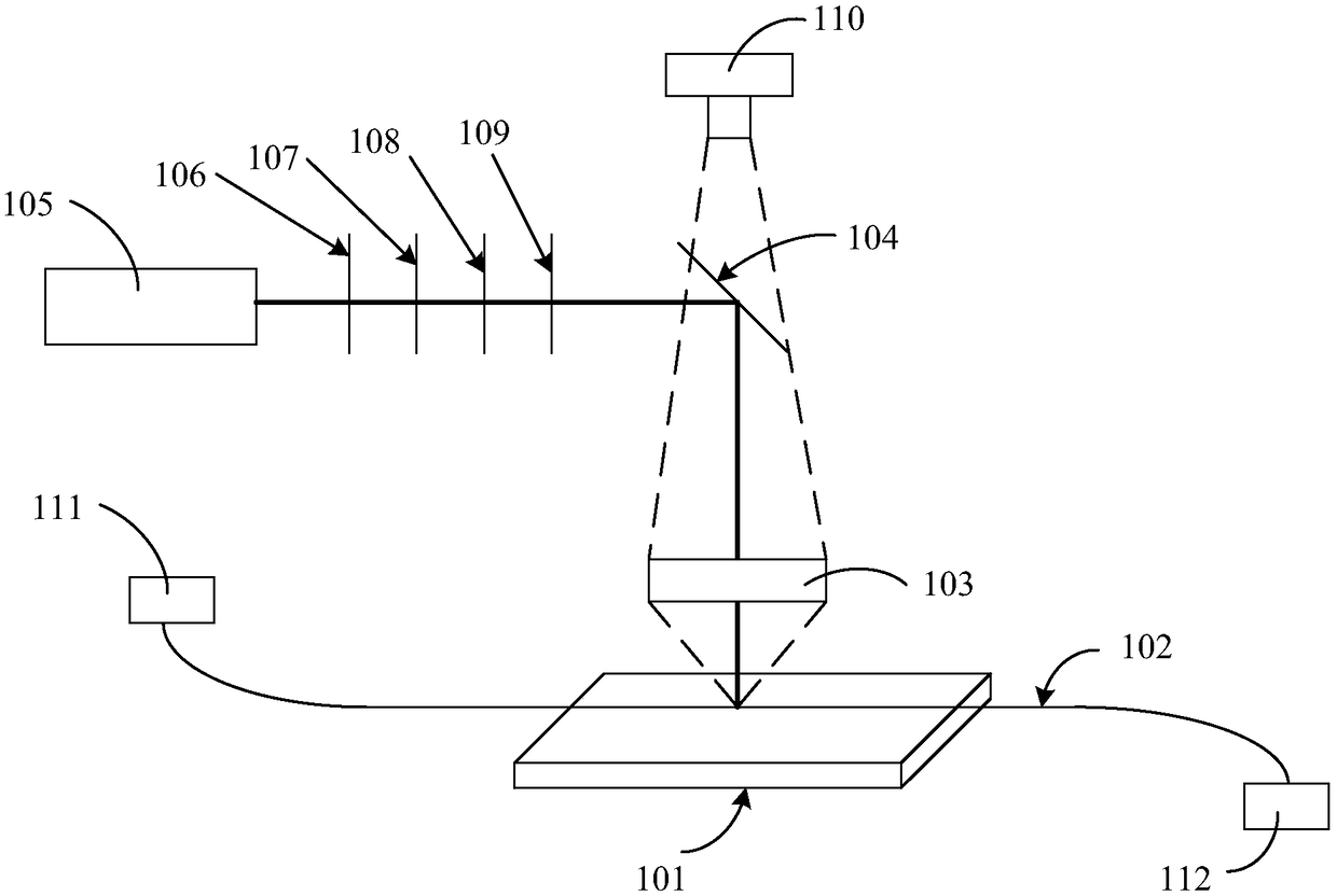
[0031] Hereinafter, embodiments of the present invention will be described with reference to the accompanying drawings, and related technical terms should be familiar to those skilled in the art. In the drawings, the same reference numerals represent the same or similar components, or the same or similar steps, unless otherwise specified. Below by specific embodiment content of the present invention is described, as figure 1 Shown the schematic diagram that the present invention makes F-P sensor, according to an embodiment ...


PUM


Abstract

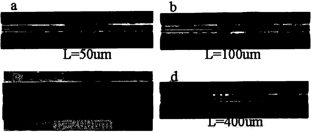
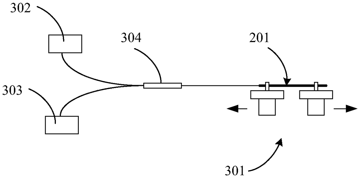
The invention provides a method for measuring strain by the aid of fiber F-P (Fabry-Perot) sensors. The method includes manufacturing the fiber F-P sensors, fixing fiber fixtures onto high-precision three-dimensional movement platforms and fixing HI-1060 fibers without coatings onto the fiber fixtures; sequentially transmitting femtosecond laser through half-wave plates, polarizers, attenuation slices and windows, reflecting the femtosecond laser via high-reflectivity mirrors, then focusing the femtosecond laser on the HI-1060 fibers and carrying out scribing and writing on the HI-1060 fibers;arranging charge coupled devices right above the high-reflectivity mirrors and observing focusing locations of the laser and morphology of the HI-1060 fibers on the fixtures; constructing strain testsystems comprising broadband light sources, circulators, the fiber F-P sensors, movable stretching platforms and spectrum analyzers; fixing the fiber F-P sensors onto the movable stretching platformsand allowing the fiber F-P sensors to generate the strain; observing and recording reflection spectra of the fiber F-P sensors by the aid of the spectrum analyzers in real time. The HI-1060 fibers with the observed morphology are processed by the laser. The method has the advantage that the fiber F-P sensors manufactured by the aid of the method are high in strain measuring sensitivity.

Description

technical field [0001] The invention relates to the technical field of optical fiber sensors, in particular to a method for measuring strain by an optical fiber F-P sensor. Background technique [0002] In recent years, fiber optic sensors have been widely used in the fields of physical, chemical, and biological sensing due to their light weight, small size, corrosion resistance, anti-electromagnetic interference, and high sensitivity. The fiber optic F-P interference sensor is a phase modulation sensor, so it has the advantages of simple structure and high sensitivity. Optical fiber F-P interference sensors are divided into intrinsic type and extrinsic type F-P interference sensors. In the extrinsic fiber optic F-P interference sensor, because the medium in the cavity is air, the light in the F-P cavity and the optical fiber produce a large coupling loss. At present, the manufacturing methods of the intrinsic type optical fiber F-P interference sensor include methods such...

Claims


Application Information

Patent Timeline
Patent Type & Authority Applications(China)
IPC IPC(8): G01B11/16
CPCG01B11/18
Inventor 祝连庆李达董明利娄小平张雯何巍李红
Owner BEIJING INFORMATION SCI & TECH UNIV
Learn More