Dynamic balancing catcher

A technology of dynamic balancing and positioning disc, applied in the field of dynamic balancing, can solve the problems of affecting working time, complicated disassembly and installation, etc., and achieve the effect of reducing labor intensity, saving processing cost and material cost, and shortening operation time.

Inactive Publication Date: 2018-06-22
嘉兴市东方万达新材料股份有限公司
View PDF0 Cites 0 Cited by
  • Summary
  • Abstract
  • Description
  • Claims
  • Application Information

AI Technical Summary

Problems solved by technology

Because most blowers are rolling bearings, the bearings, counter wheels and other components need to be removed first during dynamic balancing, and then the counter wheels are installed separately. After the balance test is completed, the bearings need to be removed again. work time

Method used


Image

  • Dynamic balancing catcher
  • Dynamic balancing catcher
  • Dynamic balancing catcher

Examples


Embodiment Construction

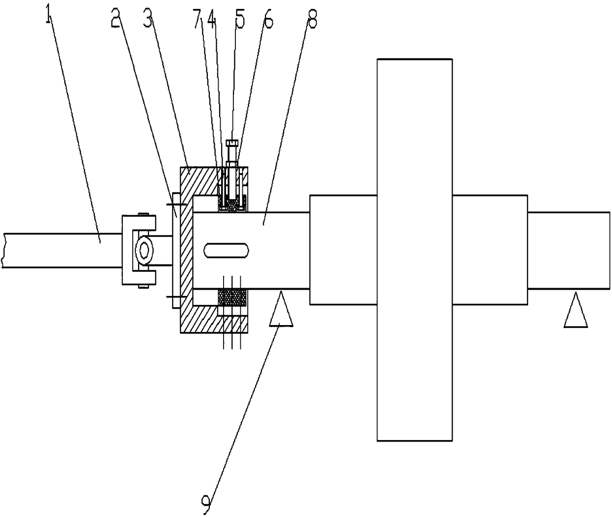
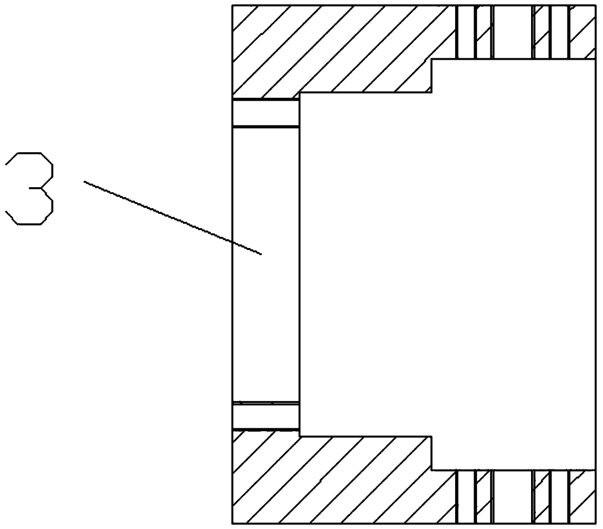
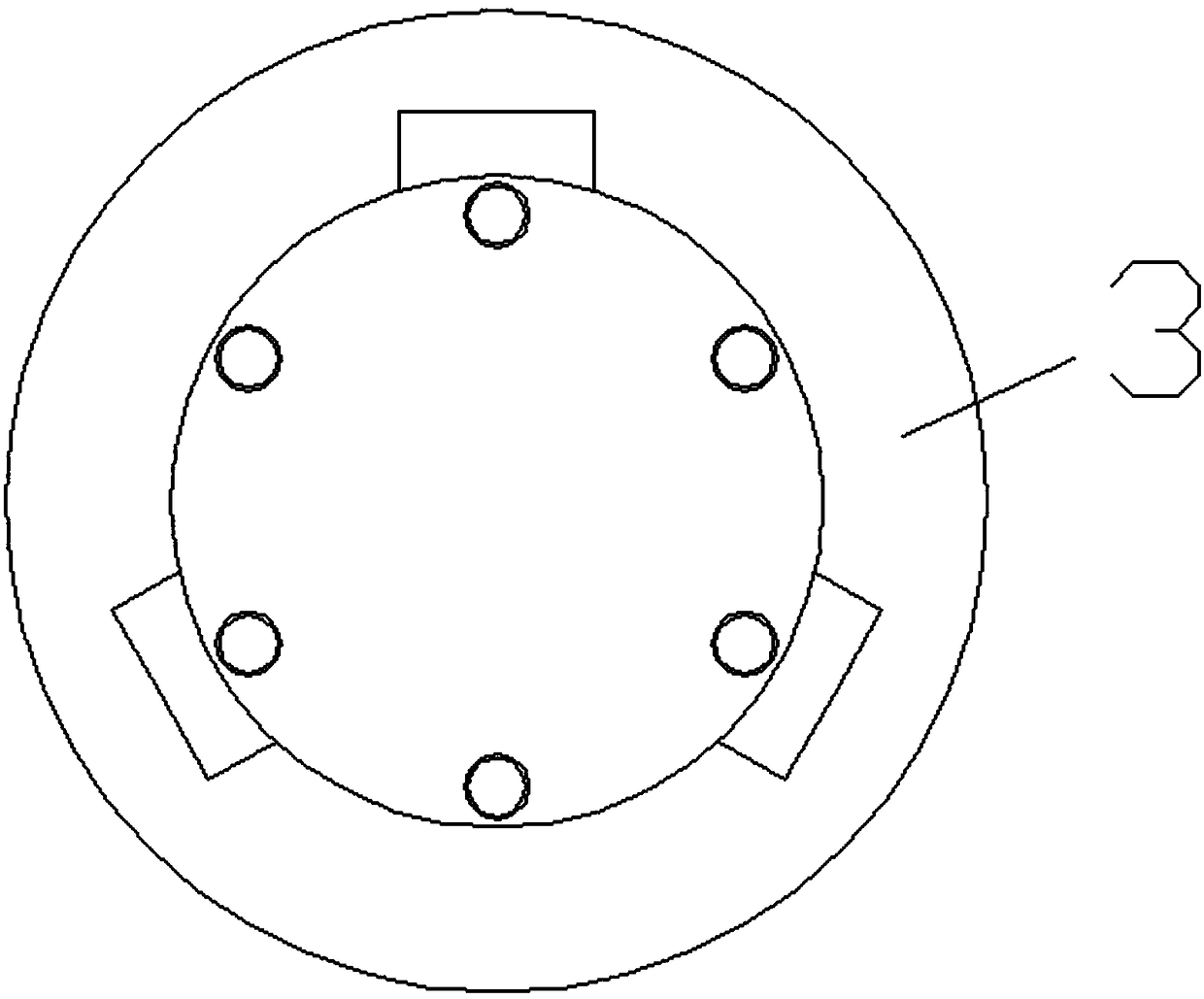
[0015] see Figure 1-Figure 5 , a dynamic balance joint provided by the embodiment of the present invention, the dynamic balance joint is used to connect the universal joint 1 and the experimental rotor 8 . The dynamic balancing handle includes a positioning plate 3, a positioning device (including a pad 7, a positioning screw 5, a nut 6 and two limit screws 4) and a small connecting plate 2. There are at least three positioning devices (three in the embodiment of the present invention). The small connecting disc 2 is fixed on one side of the positioning disc 3, and the universal joint 1 is fixed on the positioning disc 3 through the small connecting disc 2. The positioning disc 3 is cup-shaped, and the positioning disc 3 has a positioning hole, and the number of the positioning holes is consistent with the number of the positioning devices (there are three in the embodiment of the present invention). The three positioning holes are evenly distributed on the same circumferen...


PUM


Abstract

The invention relates to the technical field of dynamic balance and especially relates to a dynamic balancing catcher. The dynamic balancing catcher is used for connecting a universal coupling and anexperimental rotor and comprises a positioning plate and positioning devices. The universal coupling is fixedly connected with the positioning plate. The at least three positioning devices are distributed on the side wall of the positioning plate. The experimental rotor is fixed on the positioning plate through the positioning devices. The dynamic balancing catcher adapts to a rotor journal by adjusting the positioning devices without separately preparing a balancing disc or mounting and dismounting a coupling, thereby greatly reducing dynamic balancing operation time, reducing labor intensity, and saving processing cost and material cost.

Description

technical field [0001] The invention relates to the technical field of dynamic balance, in particular to a dynamic balance handle. Background technique [0002] Dynamic balancing technology is a key technology in the maintenance of rotating machinery and equipment. For horizontal dynamic balancing machines, the experimental rotor mainly has two connection methods: motor-driven universal coupling and air pump-driven belt. For the connection mode driven by the air pump, due to the flexible connection mode in which the belt wraps the rotor, in the actual dynamic balance, the vibration caused by the imbalance of the rotor cannot be completely reflected on the vibration measuring probe, but partly absorbed by the driving belt, and at the same time The rotation speed of the rotor is unstable during the experiment due to belt slippage, which affects the dynamic balance accuracy. The connection mode of the universal coupling driven by the motor is a rigid connection, and the mainte...

Claims


Application Information

Patent Timeline
IPC IPC(8): G01M1/02
CPCG01M1/02
Inventor 孙宇明
Owner 嘉兴市东方万达新材料股份有限公司
Why Eureka
Try Eureka