Heating circuit and kitchen equipment

A technology for heating circuits and control circuits, applied in the fields of heating circuits and kitchen equipment

Inactive Publication Date: 2018-06-26
贵州金黔科技有限公司
View PDF0 Cites 0 Cited by
  • Summary
  • Abstract
  • Description
  • Claims
  • Application Information

AI Technical Summary

Problems solved by technology

There is room for improvement in the safety, intell...

Method used


Image

  • Heating circuit and kitchen equipment
  • Heating circuit and kitchen equipment

Examples


Embodiment 1

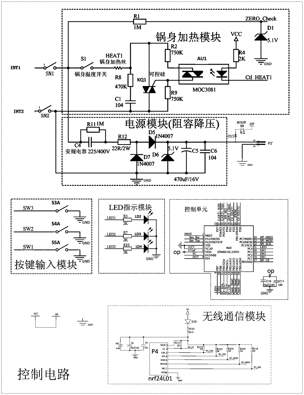
[0117] Implementation example 1. heating circuit, is characterized in that:

[0118] including control circuits;

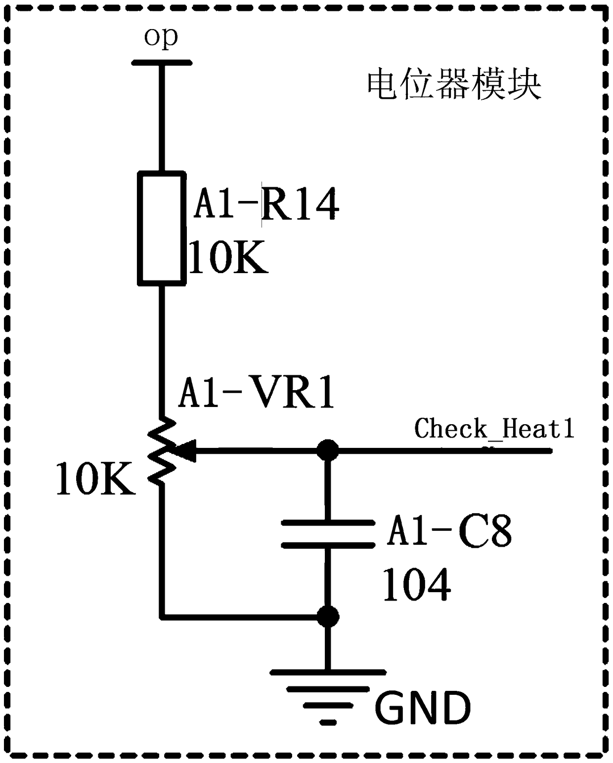
[0119] Also includes potentiometer module;

[0120] The control circuit includes the first input point (INT1), the second input point (INT2), the first safety switch (SN1), the second safety switch (SN2), the eleventh diode (D11), jumper (K1), output interface (P2'), control power point (OP), location (GND), pot body heating module, power module, key input module, LED indicator module, control unit, wireless communication module;

[0121] In the control circuit: the first end of the No. 1 safety switch (SN1) is connected to the No. 1 input point (INT1);

[0122] In the control circuit: the first end of the second safety switch (SN2) is connected to the second input point (INT2);

[0123] The control unit of the control circuit includes a microcontroller (AU2), the seventh capacitor (C7), the tenth capacitor (C10), and the eleventh capacitor (C11);

[0124] In ...

Embodiment 2

[0212] Implementation example 2, the heating circuit as described in implementation example 1, further: the resistance value of the third resistor (R3) of the LED indicator module of the control circuit is 2 kohms.

Embodiment 3

[0213] Implementation example 3, the heating circuit as described in implementation example 1, further: the model of the first optical coupler (AU1) of the pan body heating module of the control circuit is MOC3081.


PUM

PropertyMeasurementUnit
Pressure valueaaaaaaaaaa

Abstract

Provided are a heating circuit and kitchen equipment. The heating circuit includes a control circuit and a potentiometer module. The kitchen equipment has the technical scheme described as above. Theheating circuit and the kitchen equipment have the advantages that the cost is low, the application is flexible, more convenience is provided for use, networking control can be achieved, and the heating circuit and kitchen equipment are safe and reliable.

Description

technical field [0001] The invention belongs to the field of electrical appliances, in particular to heating circuits and kitchen equipment technical background [0002] Electric rice cooker is also called electric cooker, electric rice cooker. It is a cooking utensil that converts electric energy into internal energy. It is easy to use, clean and hygienic, and has multiple operating functions such as steaming, boiling, stewing, and simmering food. Common electric rice cookers are divided into three categories: heat preservation automatic type, timing heat preservation type and new microcomputer control type. Now it has become a daily household appliance, and the invention of the rice cooker has reduced the time that many families spend on cooking. There is room for improvement in the safety, intelligence and service life of the existing electric rice cooker. Contents of the invention [0003] In order to solve the above technical problems, the present invention propose...

Claims


Application Information

Patent Timeline
IPC IPC(8): A47J36/24A47J27/00
CPCA47J36/2483A47J27/004
Inventor 金松吴碧洋
Owner 贵州金黔科技有限公司
Why Eureka
Try Eureka