Automobile rotation shaft movable sealing device

A movable seal and shaft technology, applied in the direction of engine seals, engine components, mechanical equipment, etc., can solve the problems of easy wear of packing and seal failure, and achieve the effect of smooth sliding, increased sealing performance and sensitive response.

Pending Publication Date: 2018-06-26
重庆乐迪机车车辆配件有限公司
View PDF5 Cites 0 Cited by
  • Summary
  • Abstract
  • Description
  • Claims
  • Application Information

AI Technical Summary

Problems solved by technology

In the traditional movable sealing device of automobile rotating shaft, the sealing cylinder is fixedly connected with the left and right pressure plates, which leads to the fact that when the rotating shaft runs out radially, the rotating shaft will compress the packing on one side of the rotating shaft, while the packing on the other side of the rotating shaft will be compressed. becomes loose, so that the packing is easily worn, which leads to seal failure

Method used


Image

  • Automobile rotation shaft movable sealing device

Examples


Embodiment 1

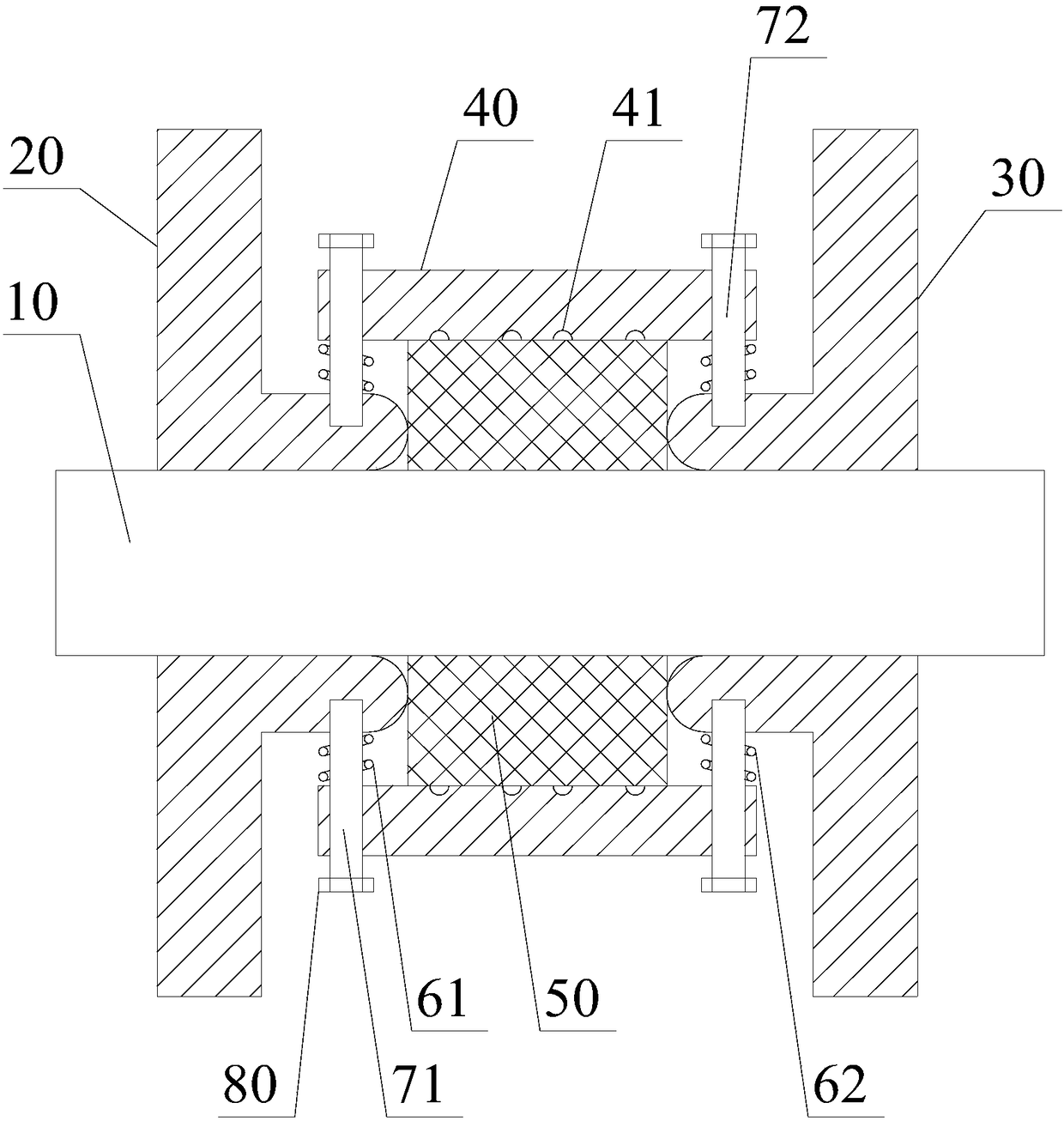
[0029] like figure 1 As shown, the movable sealing device of the automobile rotating shaft includes the rotating shaft 10, the left sealing cylinder 20, the right sealing cylinder 30, the middle sealing cylinder 40, the sealing packing 50, the first spring 61, the second spring 62, the first fixing bolt 71, the second Fixing bolt 72 and nut 80;

[0030] The middle sealing cylinder 40 is sleeved on the rotating shaft 10, and there is an annular sealing space between the middle sealing cylinder 40 and the rotating shaft 10; the left sealing cylinder 20 and the right sealing cylinder 30 are both sleeved on the rotating shaft 10. On the rotating shaft 10, the left sealing cylinder 20 and the right sealing cylinder 30 are respectively located on the left side and the right side of the middle sealing cylinder 40; one end of the left sealing cylinder 20 and the right sealing cylinder 30 both extend into the In the sealed space; the sealing packing 50 is arranged in the sealed space;...

Embodiment 2

[0035] like figure 1 As shown, in this embodiment, on the basis of Embodiment 1, both ends of the first fixing bolt 71 are threaded sections, and the middle part of the first fixing bolt 71 is slidably matched with the middle sealing cylinder 40 the smooth segment;

[0036] Both ends of the second fixing bolt 72 are threaded sections, and the middle part of the second fixing bolt 72 is a smooth section that slidably fits with the middle sealing cylinder 40 .

[0037] Both the first fixing bolt 71 and the second fixing bolt 72 have a smooth surface that slidably cooperates with the middle sealing cylinder 40 , so that the middle sealing cylinder 40 can slide more smoothly and react more sensitively.

Embodiment 3

[0039] like figure 1 As shown, in this embodiment, on the basis of Embodiment 1 or 2, one end face of the left sealing cylinder 20 extending into the sealed space is a protruding arc surface;

[0040] One end surface of the right sealing cylinder 30 extending into the sealed space is a convex arc surface.

[0041] Both the left sealing cylinder 20 and the right sealing cylinder 30 have arc surfaces without sharp corners, so as to prevent the sealing packing 50 from breaking due to the sharp corners at the ends of the left sealing cylinder 20 and the right sealing cylinder 30 .


PUM


Abstract

The invention discloses an automobile rotation shaft movable sealing device. The automobile rotation shaft movable sealing device comprises a rotation shaft, a left sealing barrel, a right sealing barrel, a middle sealing barrel, sealing filler, a first spring, a second spring, a first fixing bolt, a second fixing bolt and nuts. When the rotation shaft jumps, the rotation shaft exerts larger forceto the sealing filler on one side of the rotation shaft, the sealing filler conducts force to the middle sealing barrel at the time, and the middle sealing barrel overcomes the elastic force of the first spring and the second spring to slightly slide in the radial direction of the rotation shaft. Accordingly, it is guaranteed that the same sealing force is formed between the sealing filler on thetwo sides of the rotation shaft and the rotation shaft, and abrasion of the sealing filler due to jumping of the rotation shaft is avoided. In the normal state, the first fixing bolt and the second fixing bolt do not make contact with the middle sealing barrel. The nuts are used for avoiding large-range sliding of the middle sealing barrel. The first spring and the second spring are used for absorbing part of radial force generated during rotation shaft jumping, and the service life of the sealing filler is further improved.

Description

technical field [0001] The invention relates to a movable sealing device for an automobile rotating shaft. Background technique [0002] In the traditional movable sealing device of automobile rotating shaft, packing is set between the sealing cylinder and the rotating shaft, and then the left and right pressure plates are used to extend into the space between the sealing cylinder and the rotating shaft to compress the packing so that the packing is close to the rotating shaft, eliminating the gap between the packing and the rotating shaft. The gap between, so as to achieve the purpose of sealing. In the traditional movable sealing device of automobile rotating shaft, the sealing cylinder is fixedly connected with the left and right pressure plates, which leads to the fact that when the rotating shaft runs out radially, the rotating shaft will compress the packing on one side, while the packing on the other side of the rotating shaft will be compressed. becomes loose, so th...

Claims


Application Information

Patent Timeline
Patent Type & Authority Applications(China)
IPC IPC(8): F16J15/16
CPCF16J15/16F16J15/166
Inventor 李彬
Owner 重庆乐迪机车车辆配件有限公司
Why Eureka
Try Eureka