Magnetic resonance imaging method and system

A magnetic resonance imaging and imaging technology, which is applied in medical science, diagnostic signal processing, sensors, etc., can solve the problems of low flexibility, long imaging time, high energy received by patients, etc.

Active Publication Date: 2018-06-29
SHANGHAI UNITED IMAGING HEALTHCARE
View PDF10 Cites 12 Cited by
  • Summary
  • Abstract
  • Description
  • Claims
  • Application Information

AI Technical Summary

Problems solved by technology

This method needs to calculate the deflection angle of the radio frequency pulse in the saturation module offline first, write it into the software with hard code, or make a table query, the flexibility is not high, and the three-pulse saturation module is used, the imaging time is longer, and the patient receives high energy unsafe

Method used


Image

  • Magnetic resonance imaging method and system
  • Magnetic resonance imaging method and system
  • Magnetic resonance imaging method and system

Examples


Embodiment 1

[0050] figure 1It is a flow chart of the magnetic resonance imaging method provided by Embodiment 1 of the present invention. This embodiment is applicable to the case of magnetic resonance imaging. This method can be executed by a magnetic resonance scanning system to image the scanning area, and the scanning area can include objects Organs and specific tissues, the specific tissue may be the tissue to be saturated, the tissue to be saturated is close to or close to the target organ, and there is blood flow in the specific tissue or there is relative motion between the specific tissue and the target organ due to breathing, swallowing, etc., the device It can be realized by means of software and / or hardware. like figure 1 As shown, the method specifically includes:

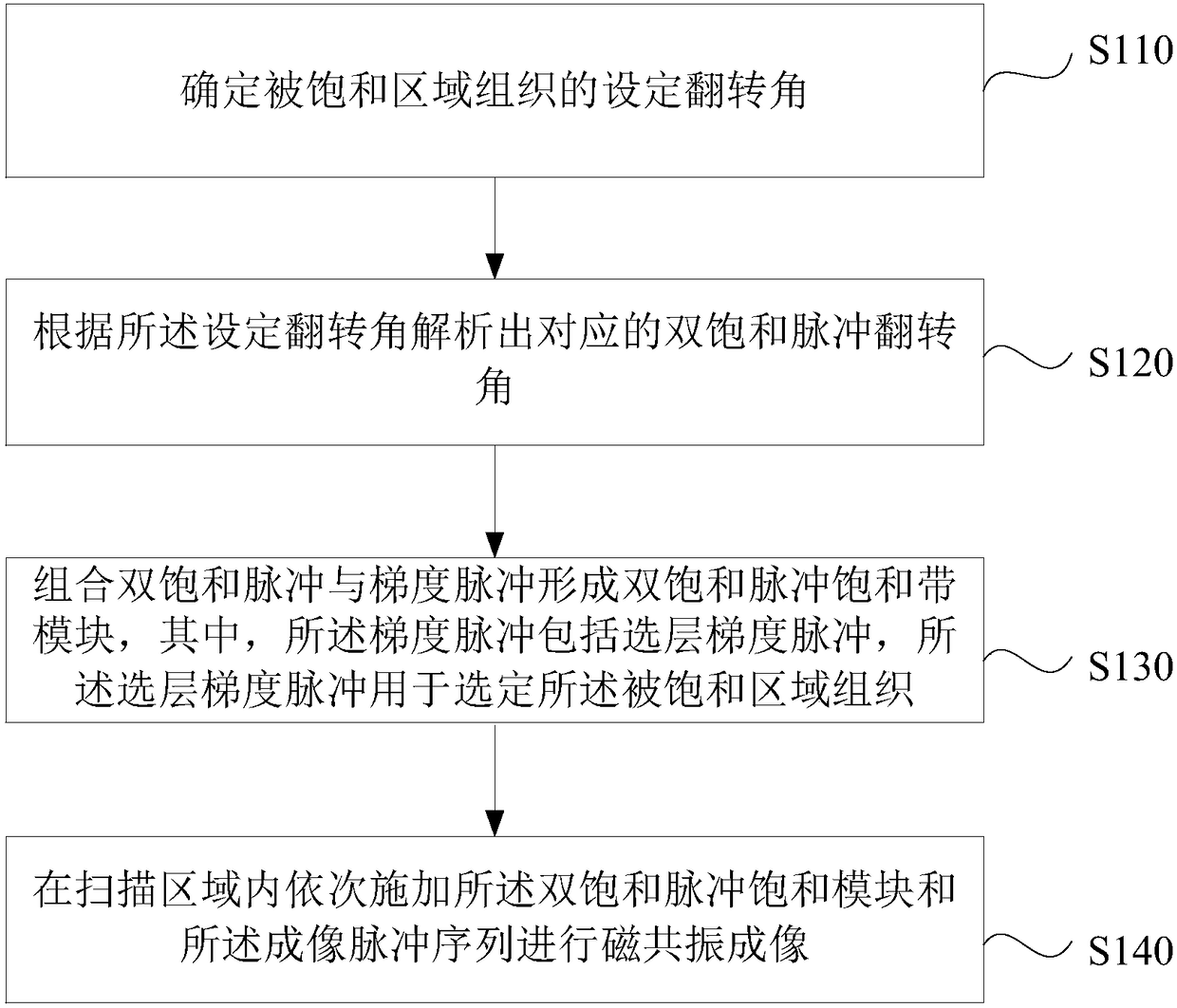
[0051] S110. Determine a preset deflection angle of a radio frequency pulse that excites a specific tissue. This step is performed prior to the imaging scan and in this example includes:

[0052] 1) Acquire sa...

Embodiment 2

[0078] image 3 Shown is a flow chart of the magnetic resonance imaging method provided by Embodiment 2 of the present invention, and this embodiment is further optimized on the basis of the foregoing embodiments. Such as image 3 As shown, the method specifically includes:

[0079] S310. Determine a preset deflection angle of a radio frequency pulse that excites a specific tissue.

[0080] Wherein, the preset deflection angle is the deflection angle α of a single pulse when the specific tissue acts on the single saturation pulse saturation module.

[0081] S320. Analyze the corresponding first saturation pulse deflection angle and second saturation pulse deflection angle according to the preset deflection angle, where the first saturation pulse and the second saturation pulse are used as double saturation pulses.

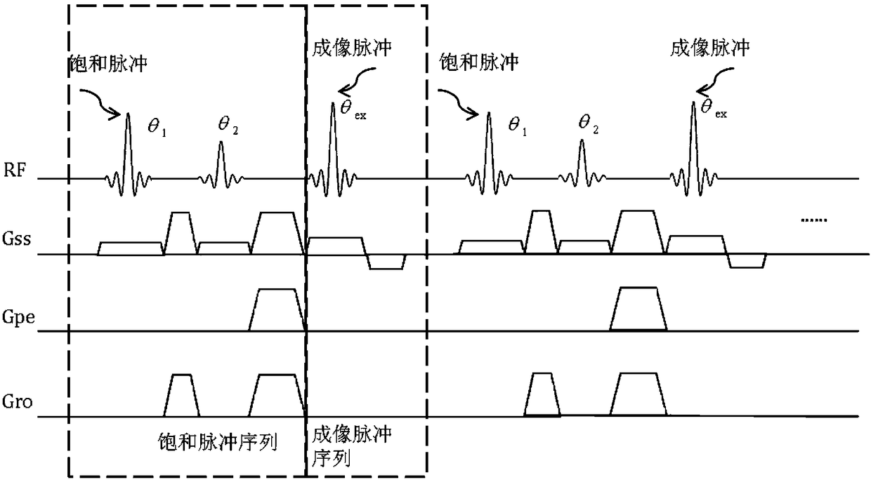
[0082] In this embodiment, the first saturation pulse and the second saturation pulse θ 1 and θ 2 Such as Figure 2b As shown, the deflection angle α of the ...

Embodiment 3

[0102] Figure 5It is a schematic structural diagram of a magnetic resonance system provided in Embodiment 3 of the present invention, Figure 5 A block diagram of an exemplary magnetic resonance system suitable for implementing embodiments of the invention is shown, Figure 5 The shown magnetic resonance system is only an example, and should not bring any limitation to the function and scope of use of the embodiments of the present invention.

[0103] As shown, the magnetic resonance system includes a cavity formed by a superconducting magnet 501 that can generate a main magnetic field that can be applied to an object (also referred to as a subject) exposed to the field. The superconducting magnet 501 can also The homogeneity of the generated main field is controlled; the gradient coil 502 and the radio frequency coil 503 are sequentially arranged inside the cavity, and the superconducting magnet 501 and the former two can be arranged coaxially. In some embodiments, a shim ...


PUM


Abstract

The invention discloses a magnetic resonance imaging method and system, wherein the method comprises: before imaging scanning, determining a preset deflection angle of a radio frequency pulse to excite specific tissues; analyzing a corresponding dual-saturated pulse deflection angle according to the preset deflection angle; combining a dual-saturated pulse and a gradient pulse to form a dual-saturated pulse saturation module, wherein the gradient pulse includes a layer-selecting gradient pulse that is used for exciting a corresponding layer of the specific tissues; executing an imaging scanning process, to be specific, applying the dual-saturated pulse saturation module and an imaging pulse sequence sequentially to a scanning area to perform magnetic resonance imaging. By carrying out magnetic resonance imaging through the dual-saturated pulse saturation module and the imaging pulse sequence, saturated band signal inhibition non-uniformity due to non-uniformity of B1 field can be overcome, and motion artifacts due to organ motion, tissue motion and other motions can be inhibited.

Description

technical field [0001] Embodiments of the present invention relate to magnetic resonance imaging technology, and in particular to a magnetic resonance imaging method and a magnetic resonance system. Background technique [0002] In the magnetic resonance imaging equipment, by placing the patient's tissue to be scanned in an imaging space in which a static magnetic field B0 is formed, the spins of protons in the to-be-scanned area are aligned to the direction of the static magnetic field, so as to generate magnetization vectors. Then, a high-frequency magnetic field is formed by transmitting radio frequency RF pulses at the resonant frequency, resulting in the occurrence of the magnetic resonance phenomenon. The phenomenon of magnetic resonance causes the flipping of the spin direction of the proton to change the magnetization vector of its proton. Magnetic resonance MR signals are generated when the spin returns the protons to their initial state of magnetization vector in ...

Claims


Application Information

Patent Timeline
Patent Type & Authority Applications(China)
IPC IPC(8): A61B5/055
CPCA61B5/055A61B5/72
Inventor 刘柳温林飞刘慧
Owner SHANGHAI UNITED IMAGING HEALTHCARE
Why Eureka
Try Eureka