Magnetic resonance imaging method and magnetic resonance system
A magnetic resonance imaging and imaging technology, used in medical science, diagnosis, diagnostic recording/measurement, etc., can solve the problems of high energy received by patients, unsafe, long imaging time, and low flexibility.
- Summary
- Abstract
- Description
- Claims
- Application Information
AI Technical Summary
Problems solved by technology
Method used
Image
Examples
Embodiment 1
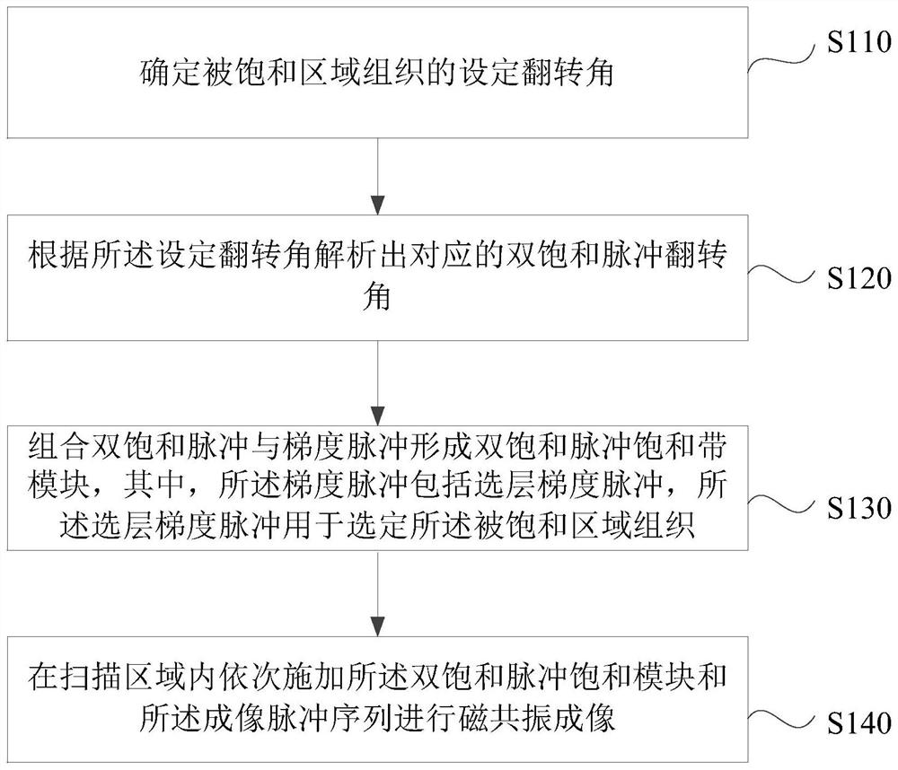
[0050] figure 1It is a flow chart of the magnetic resonance imaging method provided by Embodiment 1 of the present invention. This embodiment is applicable to the case of magnetic resonance imaging. This method can be executed by a magnetic resonance scanning system to image the scanning area, and the scanning area can include objects Organs and specific tissues, the specific tissue may be the tissue to be saturated, the tissue to be saturated is close to or close to the target organ, and there is blood flow in the specific tissue or there is relative motion between the specific tissue and the target organ due to breathing, swallowing, etc., the device It can be realized by means of software and / or hardware. Such as figure 1 As shown, the method specifically includes:
[0051] S110. Determine a preset deflection angle of a radio frequency pulse that excites a specific tissue. This step is performed prior to the imaging scan and in this example includes:
[0052] 1) Acquire...
Embodiment 2
[0078] image 3 Shown is a flow chart of the magnetic resonance imaging method provided by Embodiment 2 of the present invention, and this embodiment is further optimized on the basis of the foregoing embodiments. Such as image 3 As shown, the method specifically includes:
[0079] S310. Determine a preset deflection angle of a radio frequency pulse that excites a specific tissue.
[0080] Wherein, the preset deflection angle is the deflection angle α of a single pulse when the specific tissue acts on the single saturation pulse saturation module.
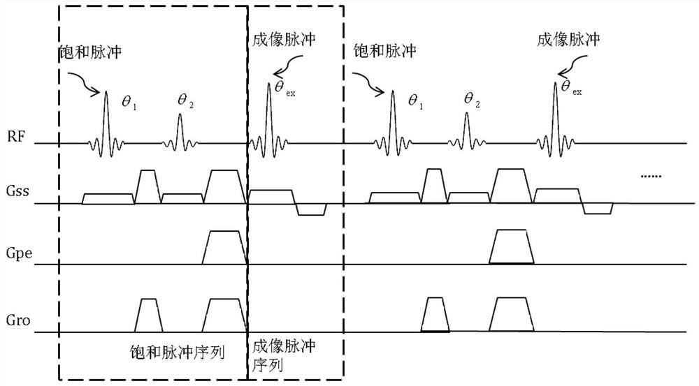
[0081] S320. Analyze the corresponding first saturation pulse deflection angle and second saturation pulse deflection angle according to the preset deflection angle, where the first saturation pulse and the second saturation pulse are used as double saturation pulses.
[0082] In this embodiment, the first saturation pulse and the second saturation pulse θ 1 and θ 2 Such as Figure 2b As shown, the deflection angle α of the ...
Embodiment 3
[0102] Figure 5It is a schematic structural diagram of a magnetic resonance system provided in Embodiment 3 of the present invention, Figure 5 A block diagram of an exemplary magnetic resonance system suitable for implementing embodiments of the invention is shown, Figure 5 The shown magnetic resonance system is only an example, and should not bring any limitation to the function and scope of use of the embodiments of the present invention.
[0103] As shown, the magnetic resonance system includes a cavity formed by a superconducting magnet 501 that can generate a main magnetic field that can be applied to an object (also referred to as a subject) exposed to the field. The superconducting magnet 501 can also The homogeneity of the generated main field is controlled; the gradient coil 502 and the radio frequency coil 503 are sequentially arranged inside the cavity, and the superconducting magnet 501 and the former two can be arranged coaxially. In some embodiments, a shim ...
PUM
 Abstract
Description
Claims
Application Information
 - R&D
- Intellectual Property
- Life Sciences
- Materials
- Tech Scout
- Unparalleled Data Quality
- Higher Quality Content
- 60% Fewer Hallucinations
Browse by: Latest US Patents, China's latest patents, Technical Efficacy Thesaurus, Application Domain, Technology Topic, Popular Technical Reports.
© 2025 PatSnap. All rights reserved.Legal|Privacy policy|Modern Slavery Act Transparency Statement|Sitemap|About US| Contact US: help@patsnap.com


