Supercharge Your Innovation With Domain-Expert AI Agents!

Rotary powder coating iron remover

A powder coating and rotary technology, applied in the direction of magnetic separation, solid separation, chemical instruments and methods, etc., can solve the problems of uneven feeding, reduce the adsorption capacity of the magnetic frame, and affect the quality of powder coatings, so as to facilitate adsorption and expand area effect

Inactive Publication Date: 2018-06-29
TIANJIN XINGZHAN POWDER COATINGS
View PDF0 Cites 0 Cited by
  • Summary
  • Abstract
  • Description
  • Claims
  • Application Information

AI Technical Summary

Problems solved by technology

The current iron removal device has a simple structure, and the staff cannot clean the internal magnetic frame in time, which reduces the adsorption capacity of the magnetic frame and affects the quality of the powder coating
When the current iron removal device is used, the powder coating is fed from the feed port, which is easy to feed unevenly and affects the iron removal operation of the powder coating

Method used


Image

  • Rotary powder coating iron remover
  • Rotary powder coating iron remover
  • Rotary powder coating iron remover

Examples


Embodiment 1

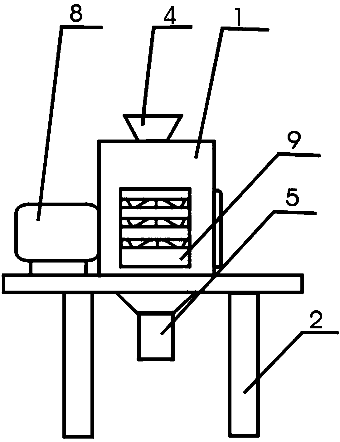
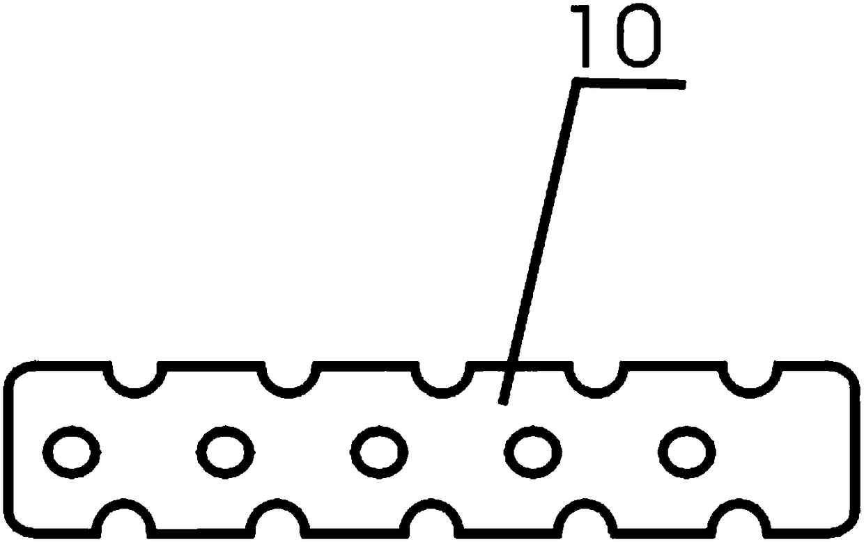
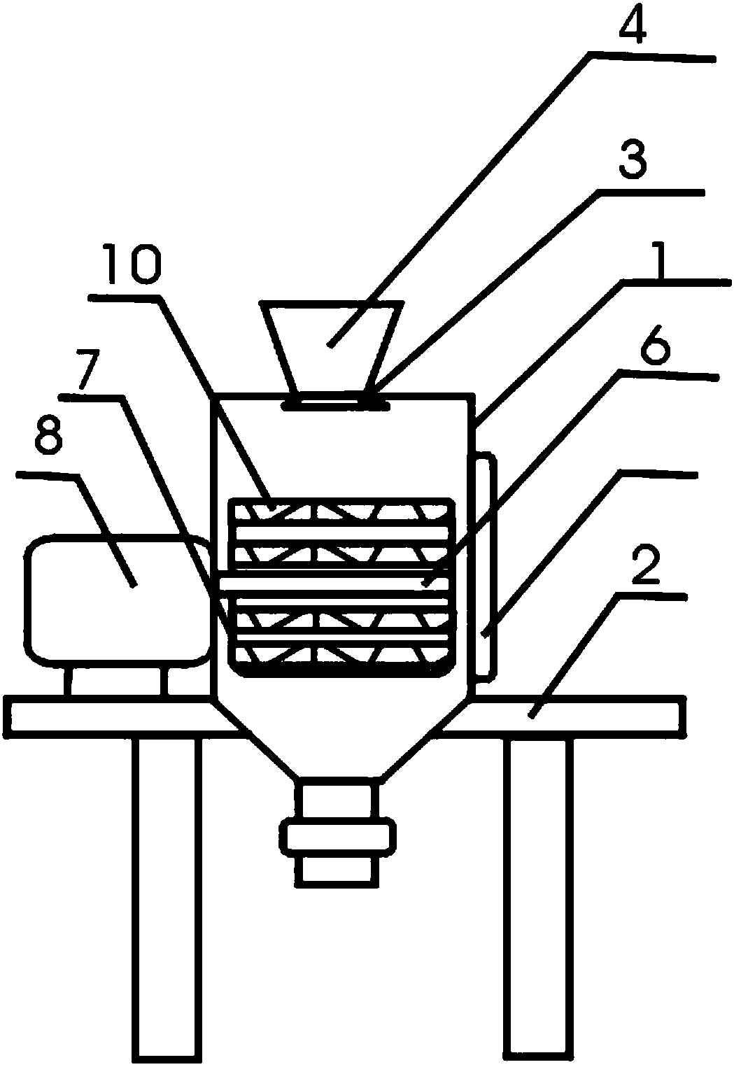
[0012] The invention is a rotary powder coating iron removal device, which includes a casing 1, a bracket 2, a diverter plate 3, a feed port 4, a discharge port 5, a rotating shaft 6, a magnetic frame 7, a motor 8, an observation window 9, and a casing 1 There is a feed port 4 on the upper side, a splitter plate 3 is installed inside the feed port 4, a discharge port 5 is provided on the lower side of the housing 1, a housing 1 and a motor 8 are installed on the upper side of the bracket 2, and the motor 8 is installed outside the housing 1 A rotating shaft 6 is installed inside the housing 1, the rotating shaft 6 is connected to the motor 8, the rotating shaft 6 is connected to the magnetic frame 7, an observation window 9 is provided on the outer side of the housing 1, and a magnetic rod 10 is provided on the magnetic frame 7, and the magnetic rod 10 is a concave-convex structure.

Embodiment 2

[0014] When in use, the present invention is opened, and the motor 8 drives the rotating shaft 6 to rotate, and then the rotating shaft 6 drives the magnetic frame 7 to rotate, and then the staff puts the powder coating into the casing 1 of the present invention through the feed port 4, and the feed port 4 is equipped with Splitter plate 3, splitter plate 3 can divert the incoming powder, so that the powder can pass through the magnetic frame 7 for impurity adsorption. When the magnetic frame 7 rotates, the iron filings are adsorbed in the concave-convex structure of the magnetic rod 10, which facilitates the adsorption of iron filings. When the magnetic frame 7 is adsorbed, the staff can observe the magnetic frame 7 in the shell 1 through the observation window 9. When it is found that the magnetic frame 7 absorbs too much iron filings, the magnetic frame 7 can be replaced or cleaned in time, which is convenient for the iron removal device in the later stage. run.


PUM


Abstract

The invention provides a rotary powder coating iron remover. The rotary powder coating iron remover is characterized in that the rotary powder coating iron remover comprises an outer shell, a support,a splitter plate, a feeding inlet, a discharging outlet, a rotary shaft, a magnetic frame, a motor and a viewing window; the feeding inlet is formed in the upper side of the outer shell; the splitterplate is mounted in the feeding inlet; the discharging outlet is formed in the lower side of the outer shell; the outer shell and the motor are mounted on the upper side of the support; the motor ismounted on the outer side of the outer shell; the rotary shaft is mounted in the outer shell and connected with the motor; and the rotary shaft is connected with the magnetic frame. The splitter plateis mounted at the feeding inlet, powder entering the remover can be split through the splitter plate and thus can penetrate through the magnetic frame for impurity adsorption conveniently. A magneticrod is mounted on the magnetic frame and is of a concave-convex structure, scrap iron is adsorbed into the concave-convex structure of the magnetic rod when the magnetic frame rotates and is adsorbedconveniently, and the adsorption area of the magnetic rod is enlarged.

Description

technical field [0001] The invention relates to the field of powder coating processing, in particular to a rotary powder coating iron removal device. Background technique [0002] After the powder coating is crushed, it needs to be iron-removed to avoid impurities such as iron filings inside the powder coating, which will affect the use of the powder coating. The structure of the current iron removal device is simple, and the staff cannot clean the internal magnetic frame in time, which reduces the adsorption capacity of the magnetic frame and affects the quality of the powder coating. When the current iron removal device is used, the powder coating is fed from the feed port, which is easy to feed unevenly and affects the iron removal operation of the powder coating. Contents of the invention [0003] According to the above technical problems, the present invention provides a rotary powder coating iron removal device, which is characterized in that it includes a casing, a...

Claims


Application Information

Patent Timeline
Patent Type & Authority Applications(China)
IPC IPC(8): B03C1/26
CPCB03C1/26
Inventor 尹振怀
Owner TIANJIN XINGZHAN POWDER COATINGS
Features
  • R&D
  • Intellectual Property
  • Life Sciences
  • Materials
  • Tech Scout
  • Unparalleled Data Quality
  • Higher Quality Content
  • 60% Fewer Hallucinations
Learn More