
Adjustable type mold machining mechanism with good clamping effect

A mold processing and adjustable technology, which is applied in metal processing equipment, perforating tools, manufacturing tools, etc., can solve the problems of poor stability of manual clamping, easy clamping of punches in the mold, and low efficiency of punching. , to achieve the effect of easy processing operation, good processing effect and increased processing quality

Active Publication Date: 2018-06-29
襄阳派尔尼模具技术有限公司
View PDF8 Cites 4 Cited by
  • Summary
  • Abstract
  • Description
  • Claims
  • Application Information

AI Technical Summary

Problems solved by technology

[0005] Aiming at the deficiencies of the prior art, the present invention provides an adjustable mold processing mechanism with good clamping effect, which has the advantages of good clamping effect and convenient operation, and solves the problem of poor stability of manual clamping and excellent clamping effect. Poor, the efficiency of punching is low, and the effect is poor, and after punching, the punch is easy to be stuck in the mold, which affects the processing efficiency

Method used


Image

  • Adjustable type mold machining mechanism with good clamping effect
  • Adjustable type mold machining mechanism with good clamping effect
  • Adjustable type mold machining mechanism with good clamping effect

Examples


Embodiment Construction

[0029] The following will clearly and completely describe the technical solutions in the embodiments of the present invention with reference to the accompanying drawings in the embodiments of the present invention. Obviously, the described embodiments are only some, not all, embodiments of the present invention. Based on the embodiments of the present invention, all other embodiments obtained by persons of ordinary skill in the art without making creative efforts belong to the protection scope of the present invention.

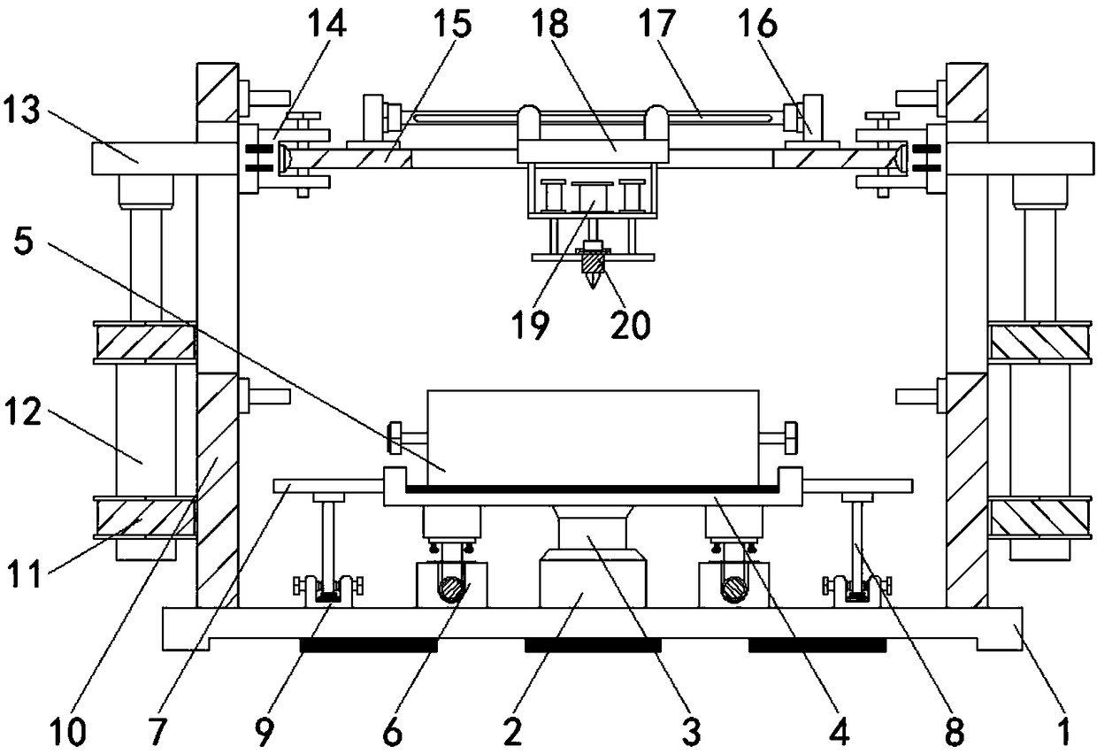
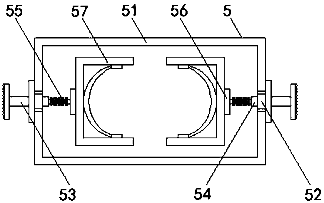
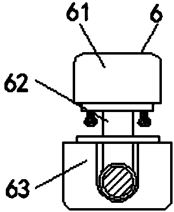
[0030] see Figure 1-4 , an adjustable mold processing mechanism with good clamping effect, including a base 1, the bottom of the base 1 is provided with a shallow groove, and the inner bottom wall of the shallow groove is fixed with an anti-slip block whose thickness is greater than the depth of the groove, increasing the base 1 and The friction force of the ground, thereby enhancing the stability, the top of the base 1 is fixedly installed with a cushion blo...


PUM


Abstract

The invention relates to the technical field of molds and discloses an adjustable type mold machining mechanism with a good clamping effect. The adjustable type mold machining mechanism with the goodclamping effect comprises a base, a cushion block is fixedly installed at the top of the base, a supporting table is fixedly installed at the top of the cushion block, a fixed seat is fixedly installed at the top of the supporting table, and a clamping mechanism is fixedly installed at the top of the fixed seat. Supporting mechanisms located on two sides of the supporting table are fixedly installed between the opposite sides of the fixed seat and the base, transverse plates are fixedly installed on two sides of the fixed seat separately, vertical rods are fixedly installed between the opposite sides of the transverse plates and the base, and fastening mechanisms located at the top of the base are fixedly installed at the ends, away from the transverse plates, of the vertical rods. Side plates located on two sides of the transverse plates are fixedly installed at the top of the base, fixed sleeves are fixedly installed on the outer sides of the side plates, and adjusting air cylindersclamped to the inner sides of the fixed sleeves are arranged on the outer sides of the side plates. The adjustable type mold machining mechanism with the good clamping effect achieves firmer clampingand a good machining effect, and is convenient for workers to use.

Description

technical field [0001] The invention relates to the technical field of molds, in particular to an adjustable mold processing mechanism with good clamping effect. Background technique [0002] Mold refers to various molds and tools used in industrial production for injection molding, blow molding, extrusion, die-casting or forging forming, smelting and stamping to obtain the required products. In short, molds are used to make shaped objects. Tool, this kind of tool is composed of various parts, and different molds are composed of different parts. It mainly realizes the processing of the shape of the object through the change of the physical state of the formed material, known as the "mother of industry". [0003] Die punching is a common processing method. The steel die punching process uses convex and concave dies made of tool steel to punch pipes. However, in the actual operation of the existing die punching device, generally Manually clamp the plate body through the clamp...

Claims


Application Information

Patent Timeline
Patent Type & Authority Applications(China)
IPC IPC(8): B21D28/28B21D28/34B21D43/00
CPCB21D28/28B21D28/34B21D43/003
Inventor 刘会
Owner 襄阳派尔尼模具技术有限公司
Learn More