
Milling machine structure with cutting fluid purification system

A purification system and cutting fluid technology, applied in chemical instruments and methods, maintenance and safety accessories, solid separation, etc., can solve the problems of difficulty in ensuring the purification effect of cutting fluid, high power consumption, large torque and power consumption, etc. , to achieve the effect of multiple recycling

Active Publication Date: 2018-06-29
珠海市立胜机械有限公司
View PDF6 Cites 0 Cited by
  • Summary
  • Abstract
  • Description
  • Claims
  • Application Information

AI Technical Summary

Problems solved by technology

[0004] The magnetic roller of the above-mentioned patent includes a magnet portion and a rubber portion, the magnet portion is distributed along 270° of the circumference of the magnetic roller, and the rubber portion is distributed along 90° of the circumference of the magnetic roller, so as to facilitate the separation of iron filings from the magnetic roller However, with such a structure, when the scraper scrapes relative to the magnetic roller, the scraper needs to push the iron filings from the magnet part to the rubber part to separate the iron filings from the magnetic roller. In this process, the iron filings and the magnet part The magnetic force between them produces greater resistance to the scraper, so the torque and power consumption required by the motor are relatively large, and the power consumption is also large
On the other hand, when the cutting fluid flows through, if it just comes into contact with the rubber part, it cannot be absorbed, that is, it is difficult to ensure the purification effect of the cutting fluid.

Method used


Image

  • Milling machine structure with cutting fluid purification system
  • Milling machine structure with cutting fluid purification system
  • Milling machine structure with cutting fluid purification system

Examples


Embodiment 1

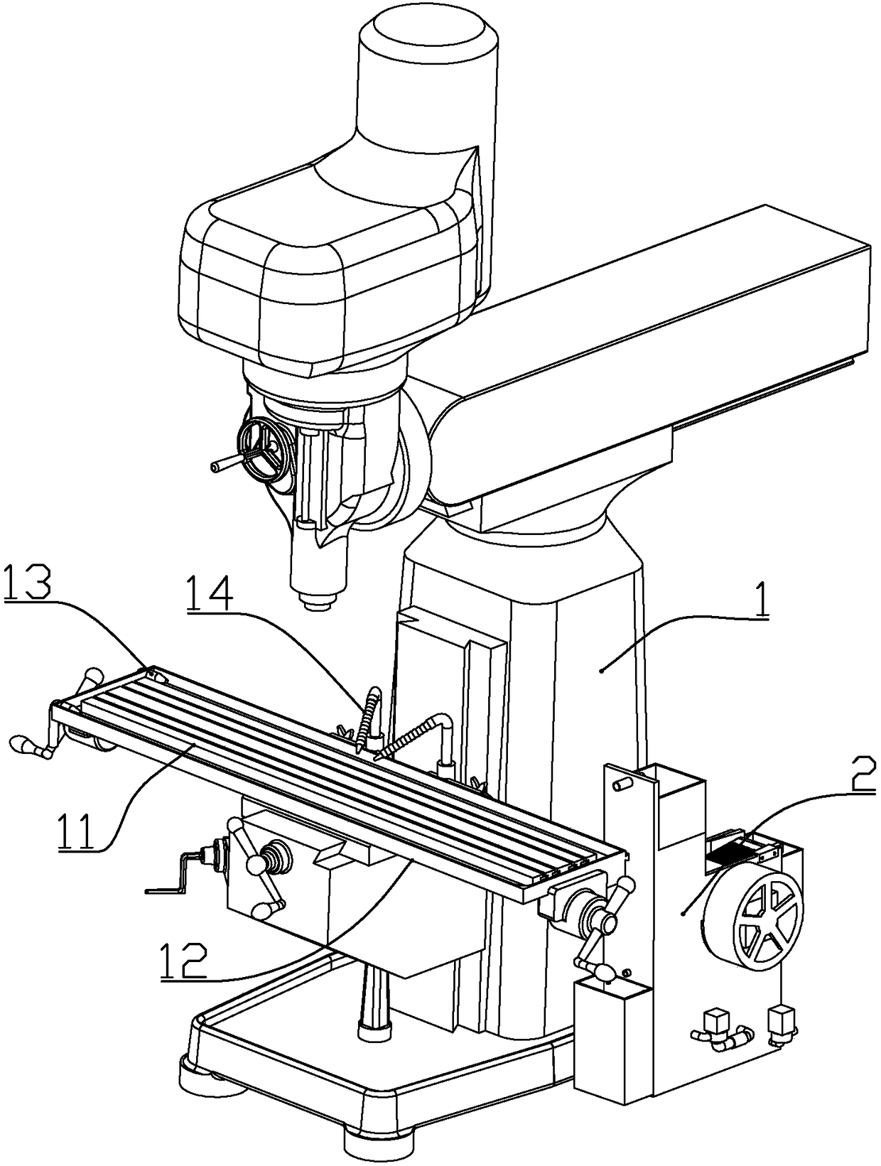
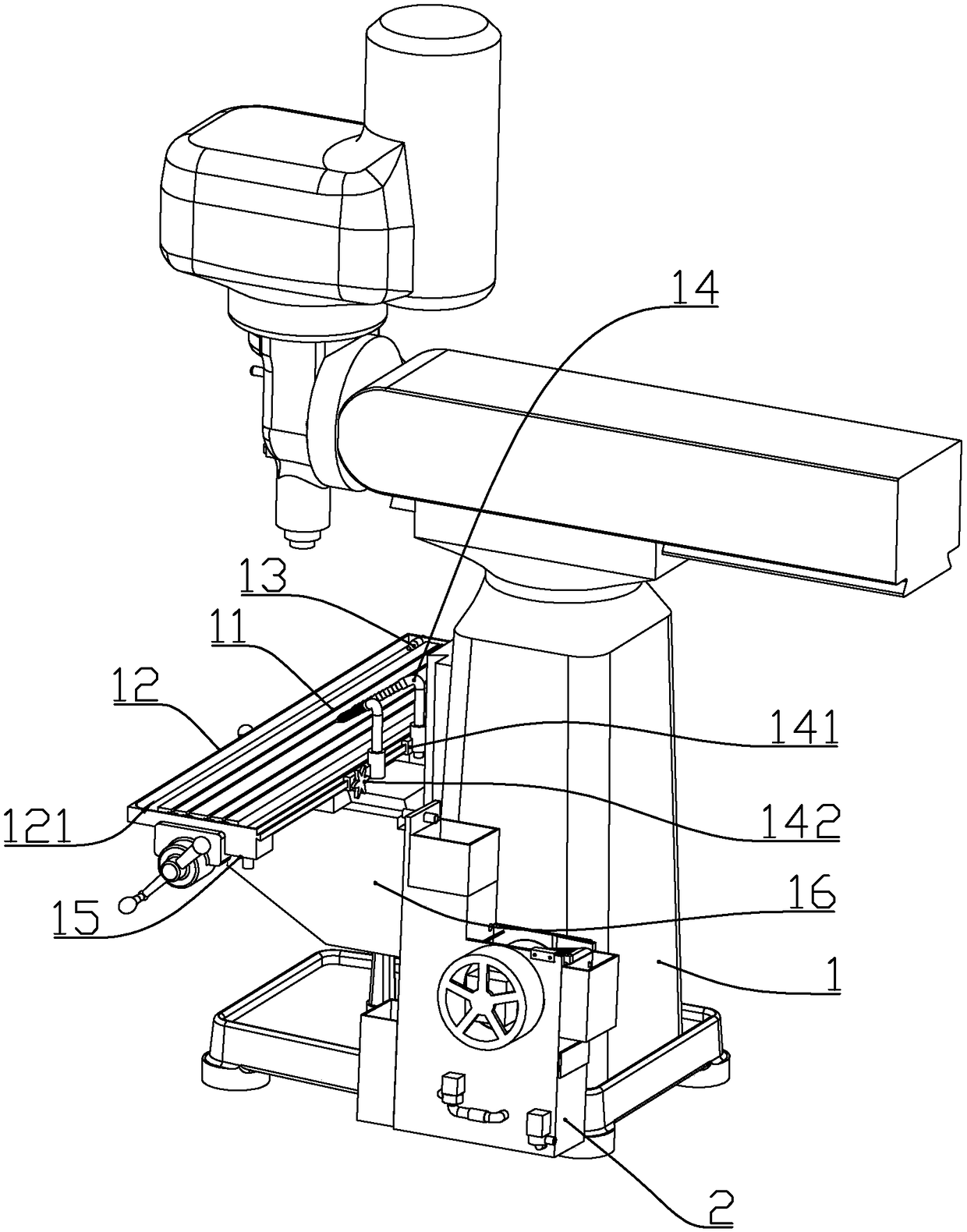
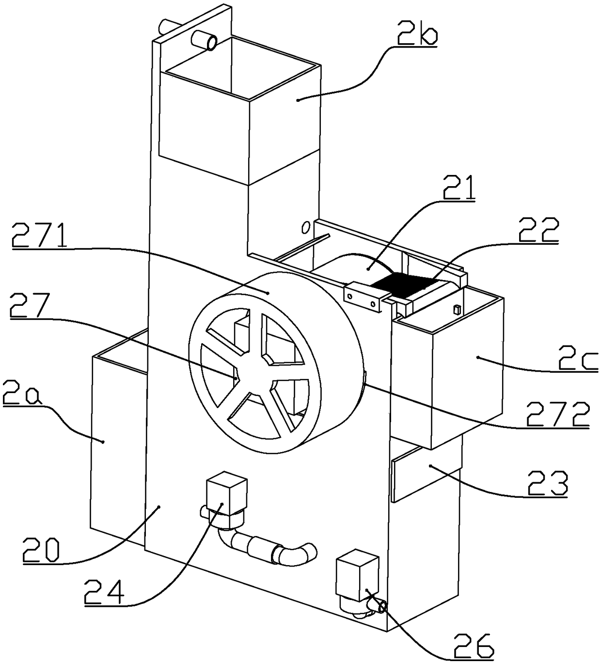
[0063] according to Figure 1 to Figure 19 As shown, the structure of a milling machine with a cutting fluid purification system described in this embodiment includes a worktable 11 installed on the main body of the milling machine 1, a collection tray 12 fixedly connected to the bottom of the worktable, and fixedly installed on the collection tray Two horizontal spray heads 13 at one end, a flushing spray head 14 slidingly installed on the collecting tray, and a cutting fluid purification device 2 connected to the horizontal spray head and the flushing spray head through pipes.

[0064] The main body of the milling machine is a conventional milling machine structure, which will not be described here.

[0065] A channel 121 for accommodating cutting fluid is formed between the inner wall of the collecting tray and the outer periphery of the worktable, and a collecting box 15 is connected below a top position of the collecting box; The oily cutting fluid is flushed into the co...

Embodiment 2

[0102] to combine Figure 20 to Figure 23 As shown, the present embodiment further makes the following improvements on the basis of embodiment 1:

[0103] The liquid return pump includes a pump body 261, a rotor assembly 262, and a pump cover 263; one end of the pump body is integrally connected with a circular pump chamber 2612, and a cylindrical cylinder communicating with the pump chamber is formed in the pump body. The inner diameter of the rotor cavity 2614 is smaller than the inner diameter of the pump cavity, and the bottom of the rotor cavity is fixedly connected with a rotor fixing shaft 2615 coaxially arranged with the rotor cavity.

[0104] A water outlet connector 2613 is formed on the side of the pump cavity; the pump cover is fixedly connected to the outer end of the pump cavity, and a water inlet connector is formed on the pump cover.

[0105] The rotor assembly is installed in the space between the pump body and the pump cover; the rotor assembly includes a ma...

Embodiment 3

[0111] This embodiment further makes the following improvements on the basis of embodiment 1 or 2:

[0112] The filter cotton includes two layers stacked from top to bottom and connected together, the thickness of the upper layer is 10mm, and the thickness of the lower layer is 15-20mm;

[0113] Each layer of filter cotton is composed of a hydrophilic and lipophilic additive layer and a filter layer that wraps the additive layer; the hydrophilic and lipophilic additive layer is made of super amphiphilic material, and the filter layer is composed of a composite filter made of cotton;

[0114] The super amphiphilic material is a nanoscale composite material, which contains a nanoscale space composed of regularly arranged hydrophilic polymer segments and lipophilic polymer segments; the composite material is a sparse porous structure, The pore size of the composite material in the upper and lower filter cottons is 45nm and 30nm successively; the composite filter cotton includes ...


PUM


Abstract

The invention discloses a milling machine structure with a cutting fluid purification system. The milling machine structure comprises a workbench, a collection disc, flushing spray heads and a cuttingfluid purification device, wherein the workbench is mounted on a milling machine main body; the collection disc is fixedly connected to the position below the workbench; the flushing spray heads aremounted on the collection disc in a sliding manner; and the cutting fluid purification device is connected with the flushing spray heads through pipes. The cutting fluid purification device comprisesa box body made of plastic. A first groove body is formed in one side of the box body. The portion, at one side of the first groove body, of the box body is provided with a second groove body and a third groove body, and the third groove body is formed below the second groove body. A magnetic roller is rotationally mounted in the second groove body and comprises a round-tube-shaped magnetic rollermain body. Multiple magnetic rod containing cavities are formed in the magnetic roller main body, and column-shaped magnetic rods are mounted in the magnetic rod containing cavities. A rotating shaftis mounted between two opposite side walls of the second groove body and connected with guiding protruding blocks, wherein the guiding protruding blocks are used for driving the magnetic rods to movetowards the middle of the magnetic roller. By means of the milling machine structure, cutting fluid can be efficiently purified in an energy-saving manner and recycled multiple times.

Description

technical field [0001] The invention belongs to a machine tool structure for mechanical processing, and in particular relates to a milling machine structure with a cutting fluid purification system. Background technique [0002] During the working process of the milling machine, a large amount of cut iron filings will be mixed in the cutting fluid. Since the cutting fluid is recycled, it is necessary to purify the iron filings in the cutting fluid. With the improvement of machining accuracy, high-speed grinding and powerful grinding technology are developing rapidly. In addition to choosing reasonable grinding parameters, the circulation quality of grinding fluid must also be improved. Existing cutting fluid purification devices are mainly filter-type purification devices, which rely on filter media to remove impurities, such as filter screen, line gap, sheet and paper tape filters. In order to avoid the accumulation of iron filings, this filter type purification device nee...

Claims


Application Information

Patent Timeline
Patent Type & Authority Applications(China)
IPC IPC(8): B23Q11/10B03C1/30
CPCB03C1/30B23Q11/10B23Q11/1069
Inventor 赵伟林小平
Owner 珠海市立胜机械有限公司
Learn More