
Machine tool for glass edge grinding and chamfering

A glass and machine tool technology, which is applied in the field of glass edge grinding and chamfering machine tools, can solve the problems of high labor intensity, many equipment, and low processing efficiency, and achieve the effects of reducing labor intensity, high processing precision, and realizing diversification

Inactive Publication Date: 2018-06-29
ZHEJIANG PUJIANG HUATONG MECHANICAL TECH CO LTD
View PDF0 Cites 1 Cited by
  • Summary
  • Abstract
  • Description
  • Claims
  • Application Information

AI Technical Summary

Problems solved by technology

[0002] The existing equipment for grinding and chamfering the edge of the glass is processed manually, the labor intensity is also high, the process is not concentrated, the processing accuracy is low, more equipment is needed, and there are many operators, and the workpiece is fixed on the working surface. On the fixture of the table, the workpiece must be manually pressed to complete the edge grinding and chamfering during the processing; when using it, only one piece can only be processed slowly, and the worker clamps it manually, which is inconvenient; when loading the workpiece, it needs Frequent manual clamping is time-consuming and labor-intensive, and the efficiency is low; and each clamping can only process one surface, the efficiency is low, and the production cost is high; moreover, workers need to feed manually during processing, and the precision of the processed workpiece is not very high , the processing efficiency is not very high

Method used


Image

  • Machine tool for glass edge grinding and chamfering
  • Machine tool for glass edge grinding and chamfering
  • Machine tool for glass edge grinding and chamfering

Examples


Embodiment Construction

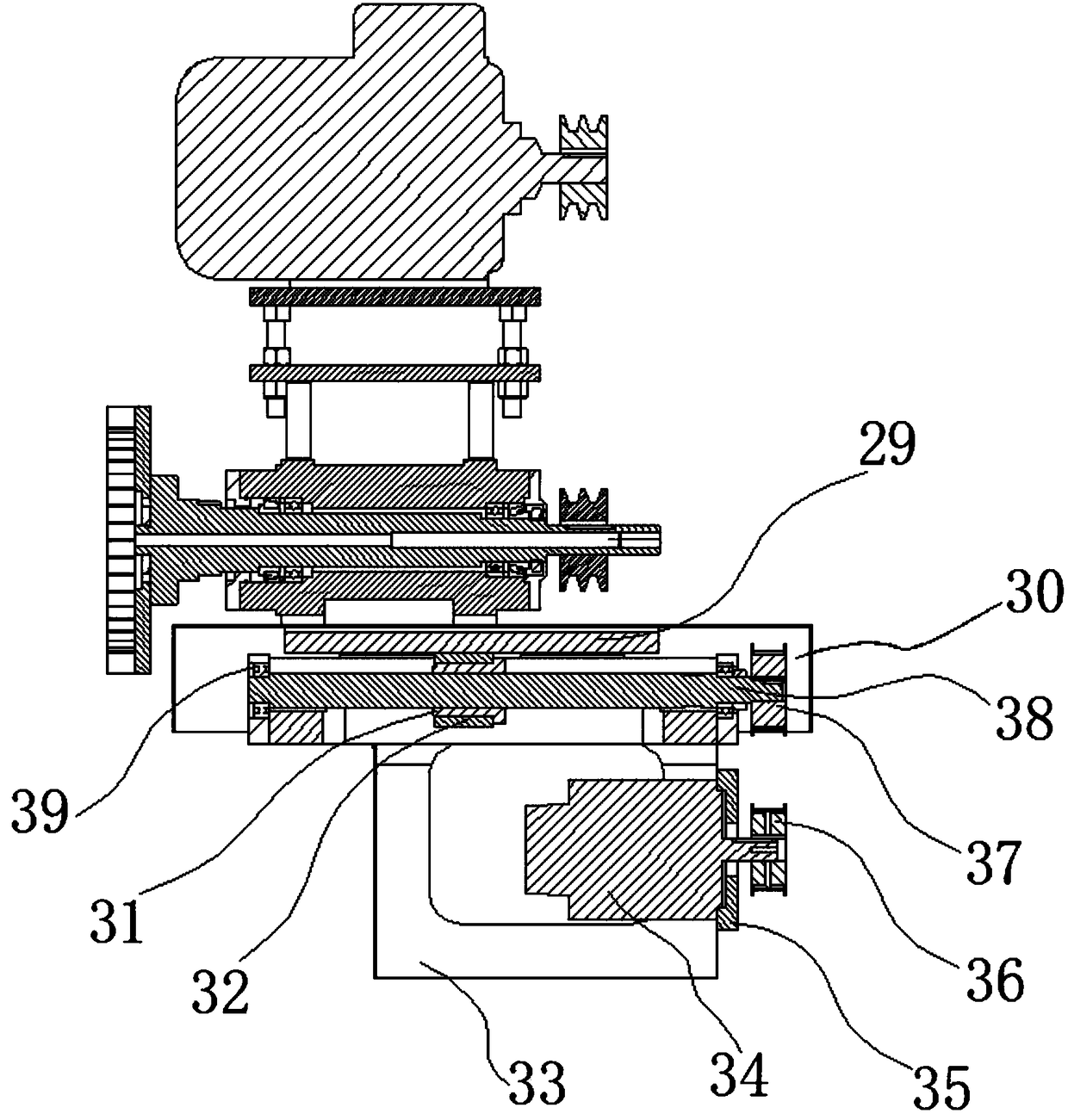
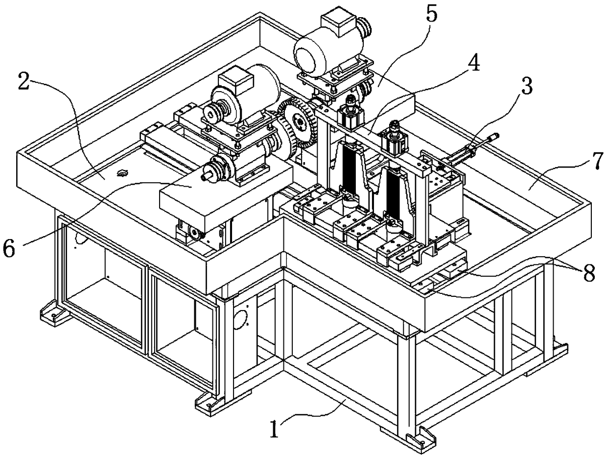
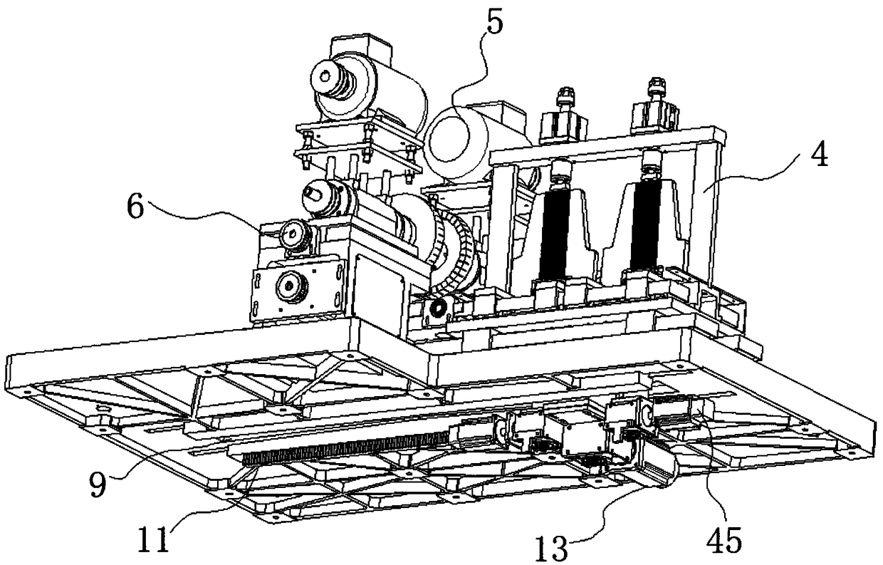
[0028] The following will clearly and completely describe the technical solutions in the embodiments of the present invention with reference to the accompanying drawings in the embodiments of the present invention. Obviously, the described embodiments are some of the embodiments of the present invention, but not all of them. Based on the embodiments of the present invention, all other embodiments obtained by persons of ordinary skill in the art without making creative efforts belong to the protection scope of the present invention.

[0029] refer to figure 1 , figure 2 , image 3 , Figure 4 As shown, a glass edge grinding and chamfering machine tool in this embodiment includes a bed 1, a frame table 2, a feeding positioning mechanism 3, a moving frame mechanism 4, a first grinding slide mechanism 5, a second grinding slide A table mechanism 6; a frame table 2 is fixedly installed on the bed 1, and a travel hole 9 is provided on the frame table 2, and two groups of mobile ...


PUM


Abstract

The invention discloses a machine tool for glass edge grinding and chamfering. The machine tool comprises a lathe bed, a rack table board, a feeding and positioning mechanism, a movable frame mechanism, a first grinding sliding table mechanism and a second grinding sliding table mechanism. The rack table board is fixedly mounted on the lathe bed, a stroke hole is formed in the rack table board, and two sets of movable frame sliding rails are fixedly mounted on the two sides of the stroke hole. The movable frame sliding rails are fixedly connected with the movable frame mechanism. The feeding and positioning mechanism is mounted on the rack table board. The first grinding sliding table mechanism and the second grinding sliding table mechanism are mounted at the positions, located on the twosides of the rear half sections of the movable frame sliding rails, of the rack table board correspondingly. A movable frame transmission mechanism is mounted at the bottom of the rack table board. The machine tool for glass edge grinding and chamfering is high in machining precision and high in machining rate; machined products are diversified; and it is important that the machine tool is convenient to use, the procedures are concentrated, automation of glass edge grinding and chamfering is achieved, and the labor intensity is reduced.

Description

technical field [0001] The invention relates to a machine tool for grinding and chamfering glass, belonging to the field of glass ornament processing machinery. Background technique [0002] The existing equipment for grinding and chamfering the edge of the glass is processed manually, the labor intensity is also high, the process is not concentrated, the processing accuracy is low, more equipment is needed, and there are many operators, and the workpiece is fixed on the working surface. On the fixture of the table, the workpiece must be manually pressed to complete the edge grinding and chamfering during the processing; when using it, only one piece can only be processed slowly, and the worker clamps it manually, which is inconvenient; when loading the workpiece, it needs Frequent manual clamping is time-consuming and labor-intensive, and the efficiency is low; and each clamping can only process one surface, the efficiency is low, and the production cost is high; moreover, ...

Claims


Application Information

Patent Timeline
Patent Type & Authority Applications(China)
IPC IPC(8): B24B9/08B24B41/00B24B41/06B24B47/12B24B41/04B24B41/02
CPCB24B9/08B24B41/005B24B41/02B24B41/04B24B41/06B24B47/12
Inventor 杨贵庭刘根平
Owner ZHEJIANG PUJIANG HUATONG MECHANICAL TECH CO LTD
Learn More