
Hardware part grinding device

A technology for hardware parts and bottom boxes, which is applied in the direction of grinding drive devices, grinding/polishing safety devices, grinding machines, etc. It can solve the problems of not being able to adjust the grinding angle, achieve the effects of improving grinding quality, prolonging service life, and reducing injuries

Inactive Publication Date: 2018-06-29
浙江固柏电力科技有限公司
View PDF5 Cites 5 Cited by
  • Summary
  • Abstract
  • Description
  • Claims
  • Application Information

AI Technical Summary

Problems solved by technology

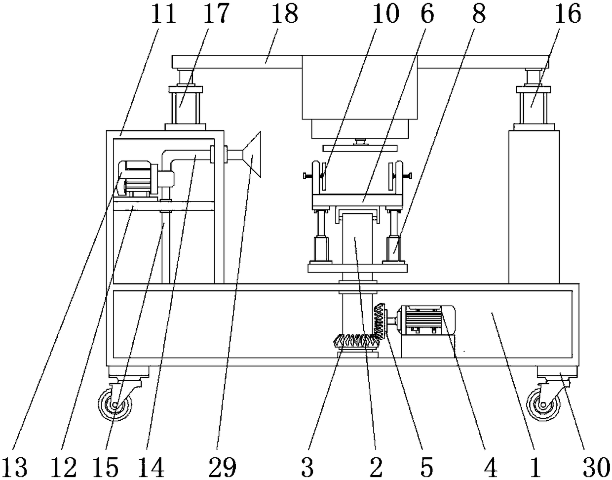
[0004] The object of the present invention is to provide a grinding device for hardware parts, which solves the problem that the existing grinding device cannot adjust the grinding angle during grinding by setting a rotatable support plate

Method used


Image

  • Hardware part grinding device
  • Hardware part grinding device
  • Hardware part grinding device

Examples


Embodiment Construction

[0025] The following will clearly and completely describe the technical solutions in the embodiments of the present invention with reference to the accompanying drawings in the embodiments of the present invention. Obviously, the described embodiments are only some, not all, embodiments of the present invention. Based on the embodiments of the present invention, all other embodiments obtained by persons of ordinary skill in the art without creative efforts fall within the protection scope of the present invention.

[0026] In describing the present invention, it is to be understood that the terms "opening", "upper", "lower", "thickness", "top", "middle", "length", "inner", "surrounding" etc. Indicating orientation or positional relationship is only for the convenience of describing the present invention and simplifying the description, and does not indicate or imply that the components or elements referred to must have a specific orientation, be constructed and operated in a sp...


PUM


Abstract

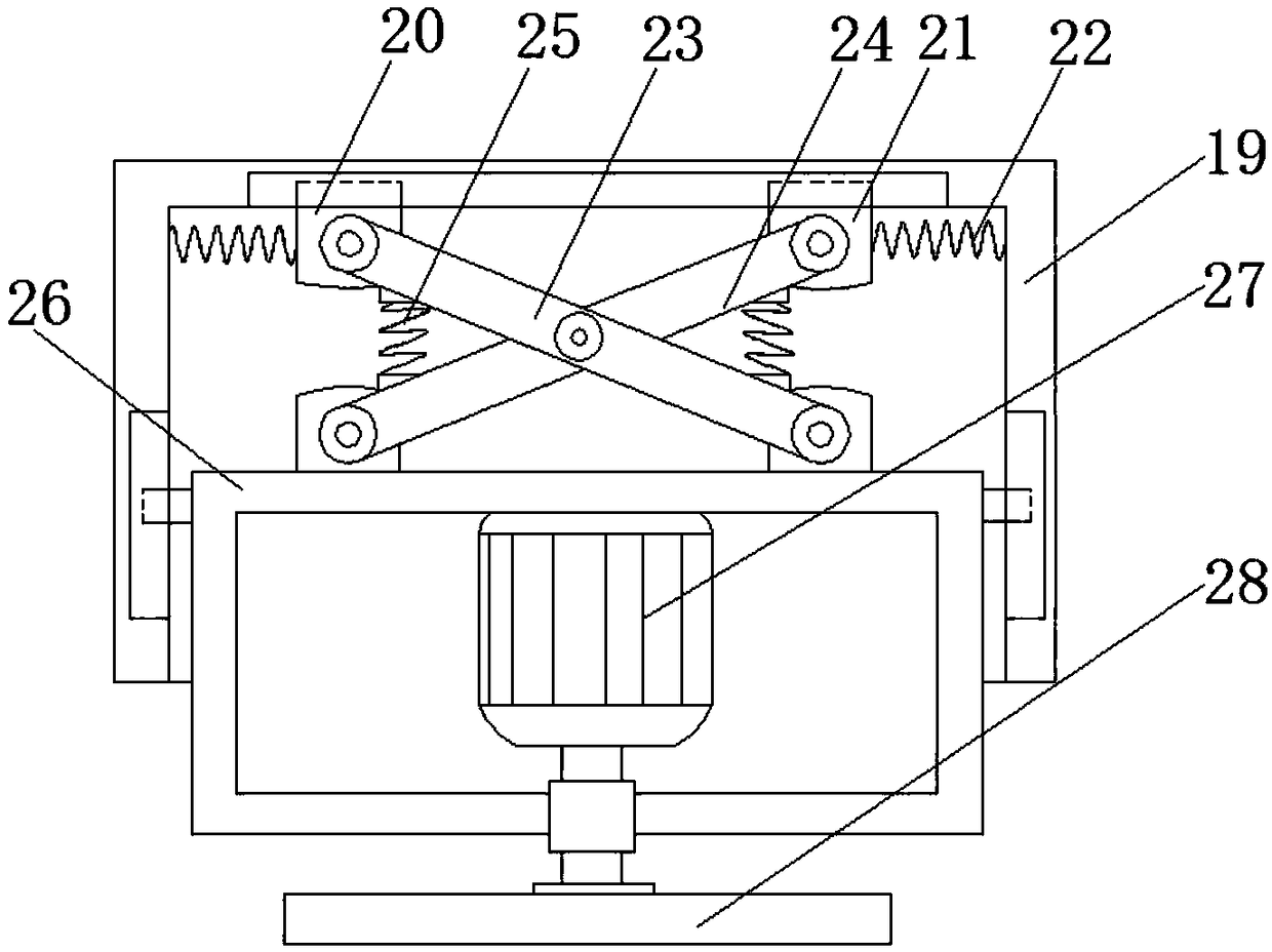
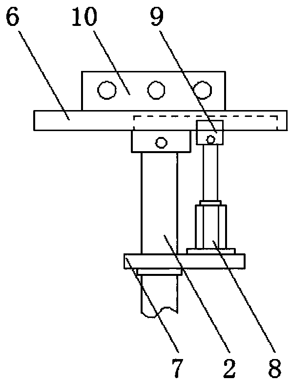
The invention discloses a hardware part grinding device, and relates to the technical field of hardware machining. The hardware part grinding device comprises a bottom box, and the bottom of an innercavity of the bottom box is rotationally connected with a rotary shaft. The top end of the rotary shaft penetrates a top plate of the bottom box and extends to the upper portion of the bottom box. A first bevel gear is fixedly mounted on the portion, located in the bottom box, of the rotary shaft, and a first rotary motor is fixedly mounted at the bottom of the inner cavity of the bottom box. A second bevel gear is fixedly mounted at an output shaft of the first rotary motor, and the second bevel gear and the first bevel gear are engaged. The end, extending to the upper portion of the bottom box, of the rotary shaft is rotationally connected with a supporting plate, and a baffle is fixedly mounted at the position, located below the supporting plate, of the surface of the rotary shaft. According to the hardware part grinding device, the rotary shaft and the supporting plate are driven to rotate through the first bevel gear and the second bevel gear, and a first hydraulic cylinder is started to drive the supporting plate to rotate; and by means of the design, the placing angle of a material can be changed in an omnibearing manner, grinding is convenient, and the grinding quality is improved.

Description

technical field [0001] The invention belongs to the technical field of hardware processing, and in particular relates to a grinding device for hardware parts. Background technique [0002] Traditional hardware products, also known as "small hardware", refer to five metals: gold, silver, copper, iron, and tin; through manual processing, they can be made into works of art or metal devices such as knives and swords. Hardware in modern society is more extensive, such as Hardware tools, hardware parts, daily hardware, construction hardware and security supplies, etc., hardware products are mostly not final consumer goods. [0003] The existing grinding and placing device generally cannot be rotated, so the operator needs to reinstall it. Such an operation is not conducive to improving work efficiency, and some equipment does not have a smoke absorbing device. In this way, the smoke generated during the grinding process is easy to pollute the atmosphere. endanger people's health....

Claims


Application Information

Patent Timeline
Patent Type & Authority Applications(China)
IPC IPC(8): B24B19/00B24B55/06B24B27/00B24B47/08B24B41/00B24B41/06
CPCB24B19/00B24B27/0007B24B27/0015B24B41/007B24B41/06B24B47/08B24B55/06
Inventor 赵建义
Owner 浙江固柏电力科技有限公司
Learn More