A lower limb assist exoskeleton device and its dynamic joint device

A power device and joint technology, applied in the field of power joint devices, can solve the problems of heavy weight, difficult to guarantee accuracy, undisclosed, etc., and achieve the effects of simplifying design complexity, precise and flexible control, and wide adaptability.

Active Publication Date: 2020-09-15
SHENZHEN CONCHIN TECH CO LTD
View PDF1 Cites 0 Cited by
  • Summary
  • Abstract
  • Description
  • Claims
  • Application Information

AI Technical Summary

Problems solved by technology

In terms of the connection structure of the upper arm and the lower arm, in order to simplify the design, some schemes fix the upper arm and the lower arm with the flexible wheel and the steel wheel of the harmonic reducer respectively, such as the 2011 master thesis of Harbin Institute of Technology "Exoskeleton lower limb power-assisted robot This method is disclosed in "Technical Research", which will cause the upper and lower arms to not be on the same plane, and a large lateral torque will be generated when the joint bears force, which is easy to damage the joint; the paper "Mechanical Design of the Hanyang Exoskeleton Assistive Robot (HEXAR)" A similar solution was also disclosed in ICCAS2014; in order to reduce the influence of the lateral torque in the above solution, crossed roller bearings can be used, but the cost is high and the problem cannot be solved fundamentally
[0004] In the prior art, a rotary encoder is required to control the motor, and the existing solutions all use photoelectric rotary encoders, which are bulky and costly, resulting in complex dynamic joint design; the paper "Mechanical Design of the Hanyang Exoskeleton Assistive Robot (HEXAR)" ICCAS2014 , the paper "Design of an electrically actuated lower extremity exoskeleton" (Advanced Robotics, Vol. 20, No. 9, pp.967–988 (2006)) and Chinese patent 201620267410.7 all disclose the same scheme
[0005] In the prior art, some torque sensors are used to measure the output torque of the motor, such as the paper "Mechanical Design of the Hanyang Exoskeleton Assistive Robot (HEXAR)" ICCAS2014 discloses such a scheme, which is costly, bulky and heavy; some use A pressure sensor is used to measure the output torque of the motor. This type of scheme is disclosed in the paper "Design of an electrically actuated lower extremity exoskeleton" (Advanced Robotics, Vol. 20, No. 9, pp. 967–988 (2006)). The structure of this scheme is relatively Complex, strict requirements for installation accuracy, and relatively high cost
[0006] In the prior art, the dynamic joint does not include a solution for measuring the relative angle of the upper arm and the lower arm. Generally, the motor encoder is used to estimate the relative angle of the upper and lower arms. The problem with this solution is that calibration is required every time the power is turned on, and the accuracy is difficult to guarantee; Neither the paper "Mechanical Design of the Hanyang Exoskeleton Assistive Robot (HEXAR)" ICCAS2014 nor the paper "Design of an electrically actuated lower extremity exoskeleton" (Advanced Robotics, Vol. 20, No. 9, pp. 967–988 (2006)) disclosed A solution for measuring the relative angle of the upper and lower arms

Method used


Image

  • A lower limb assist exoskeleton device and its dynamic joint device
  • A lower limb assist exoskeleton device and its dynamic joint device
  • A lower limb assist exoskeleton device and its dynamic joint device

Examples


Embodiment 1

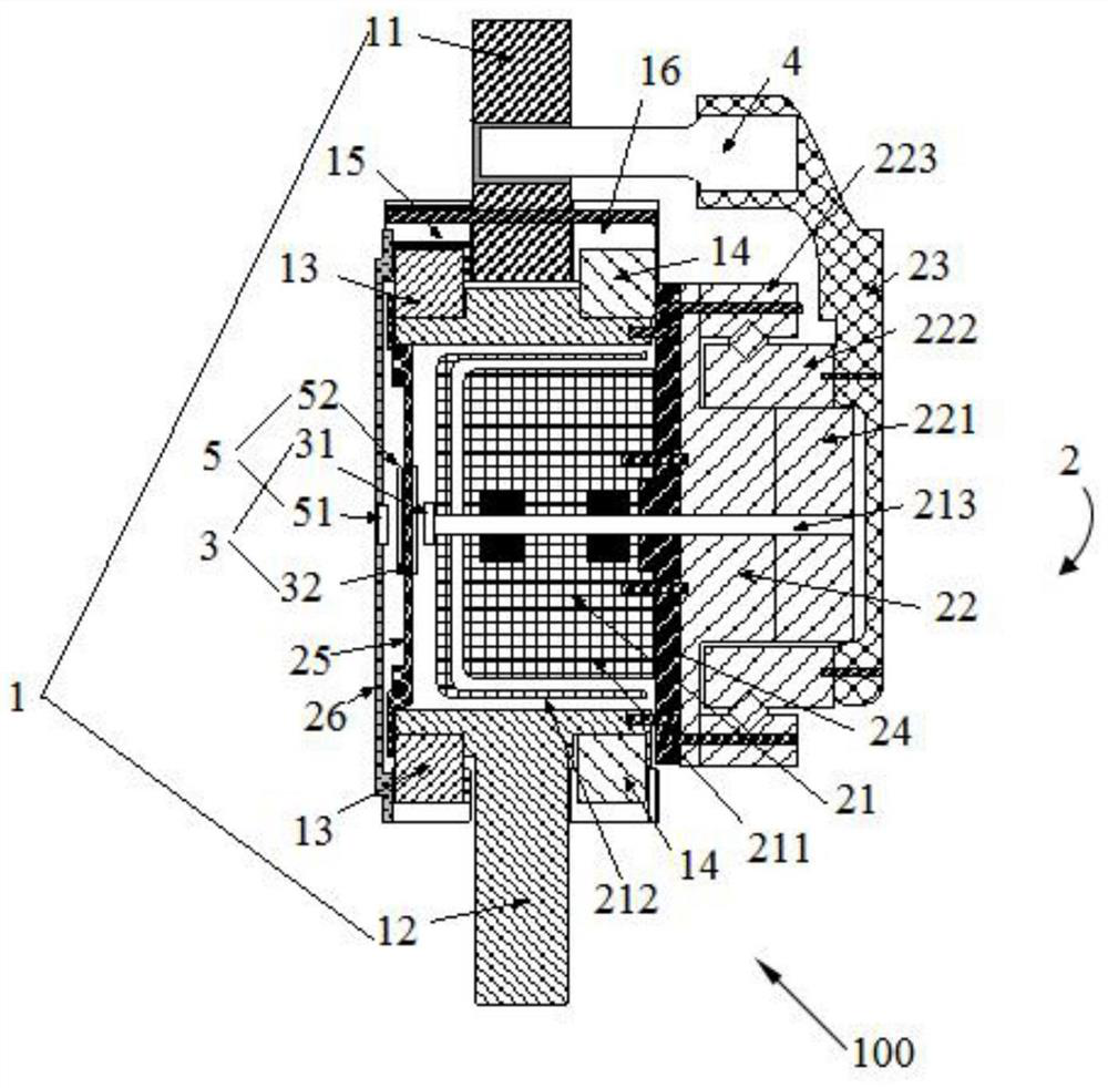
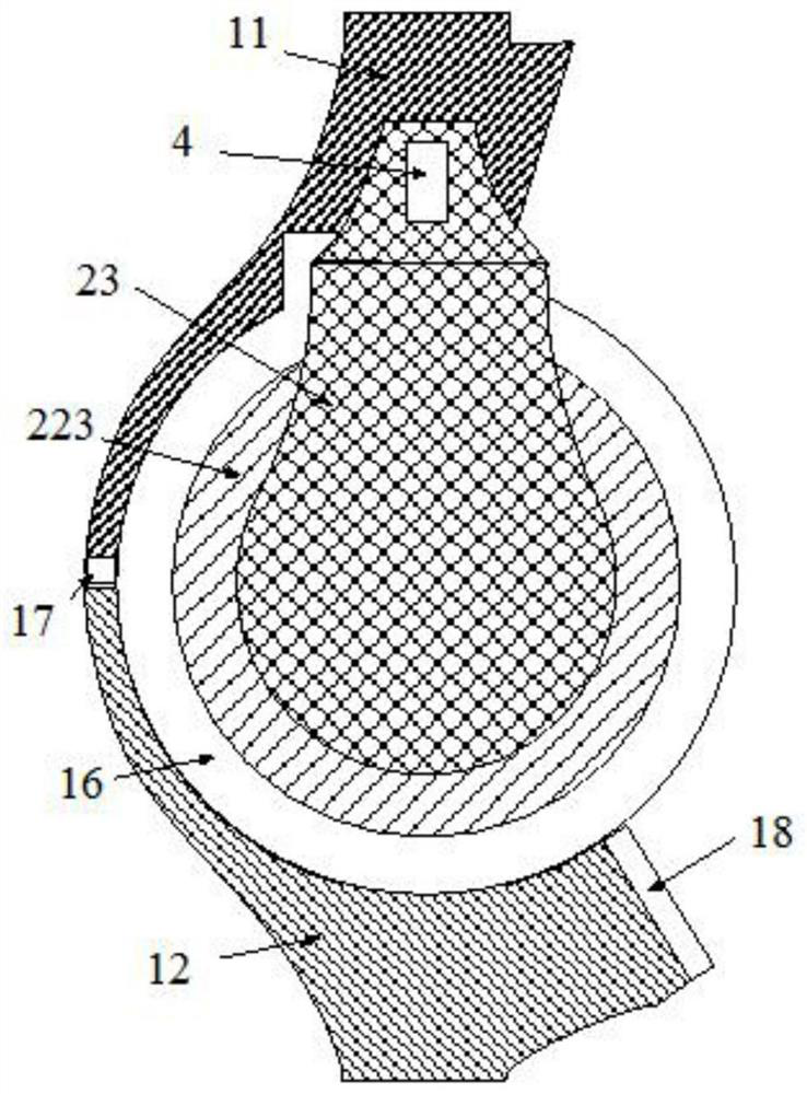
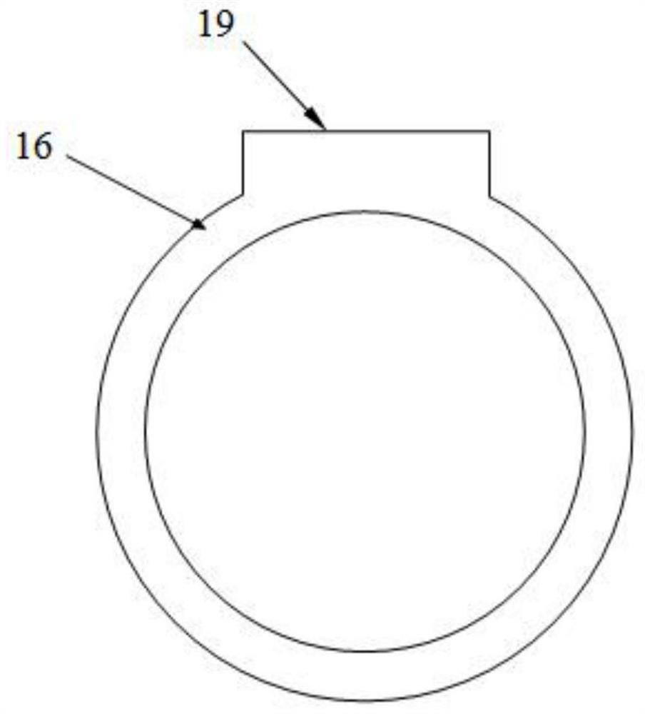
[0040] A power joint device 100, comprising a joint body 1 and a power device 2, the joint body includes an upper arm 11 and a lower arm 12, the upper part of the lower arm 12 is a cavity with openings on both sides, and the two sides of the cavity A first bearing 13 and a second bearing 14 are respectively sleeved on the outer wall, and a first bearing sleeve 15 and a second bearing sleeve 16 are respectively sleeved outside the first bearing 13 and the second bearing 14. The first bearing sleeve 15 and the second bearing sleeve 16 clamp the upper arm 11 in the middle, the first bearing sleeve 15 and the second bearing sleeve 16 have handles 19, and are tightly fixedly connected with the upper arm 11 through the respective handles 19 , so that the upper arm 11 and the lower arm 12 can rotate relatively freely, and both have a strong load-bearing capacity; the upper arm 11 and the lower arm 12 are distributed on a plane, so that the joint device will not produce Lateral torque...

Embodiment 2

[0047] A power joint device 100, comprising a joint body 1 and a power device 2, the joint body includes an upper arm 11 and a lower arm 12, the upper part of the lower arm 12 is a cavity with openings on both sides, and the two sides of the cavity A first bearing 13 and a second bearing 14 are respectively sleeved on the outer wall, and a first bearing sleeve 15 and a second bearing sleeve 16 are respectively sleeved outside the first bearing 13 and the second bearing 14. The first bearing sleeve 15 and the second bearing sleeve 16 clamp the upper arm 11 in the middle, the first bearing sleeve 15 and the second bearing sleeve 16 have handles 19, and are tightly fixedly connected with the upper arm 11 through the respective handles 19 , so that the upper arm 11 and the lower arm 12 can rotate relatively freely, and both have a strong load-bearing capacity; the upper arm 11 and the lower arm 12 are distributed on a plane, so that the joint device will not produce Lateral torque...

Embodiment 3

[0057] A dynamic joint device 100, such as Figure 1-3 As shown, it includes a joint main body 1 and a power unit 2. The joint main body includes an upper arm 11 and a lower arm 12. The upper part of the lower arm 12 is a cavity with openings on both sides. The outer walls of the cavity are respectively covered with Connected with a first bearing 13 and a second bearing 14, the first bearing 13 and the second bearing 14 are respectively sleeved with a first bearing sleeve 15 and a second bearing sleeve 16, and the first bearing sleeve 15 and the second Bearing sleeve 16 clamps upper arm 11 in the middle, and described first bearing sleeve 15 and second bearing sleeve 16 have shank 19, and all through respective shank 19 and upper arm 11 are tightly fixedly connected together by screw, so described The upper arm 11 and the lower arm 12 can rotate relatively freely, and both have a strong load-bearing capacity; the upper arm 11 and the lower arm 12 are distributed on a plane, so...


PUM


Abstract

The invention relates to a power joint device. The device comprises a joint body, a power device and a measuring device; the measuring device comprises a first angular measuring device, the first angular measuring device comprises a first magnet and a first magnetic field induction circuit, the first magnet is connected with one end of a motor output shaft, and is close to a first motor cover plate, the first magnetic field induction circuit is arranged on the inner side of the first motor cover plate and is close to the first magnet, a motor rotates to drive the motor output shaft to rotate,and further drive the first magnet to rotate, and the first magnetic field induction circuit induces the rotating angle of the first magnet so as to measure the rotating angle of the motor. Through the first magnet and the first magnetic field induction circuit which are in the non-contact coupling manner, measuring of the motor rotating angle is achieved, mechanical friction losses are avoided, simpleness, lightness, thinness and low cost are achieved, compared with an existing integrated type encoder scheme, mechanical structural design complexity is greatly simplified, a magnetic field generated by the magnet is a static magnetic field, the environment interference influence is avoided, and reliability is high.

Description

technical field [0001] The invention relates to a dynamic joint device, in particular to a dynamic joint device used in the field of exoskeleton robots. Background technique [0002] The field of robotics requires the application of dynamic joints widely. The exoskeleton robots used for human wearables generally have multiple dynamic joints. It is also necessary to integrate force sensors, angle sensors, and motor rotary encoders; at the same time, it is also necessary for the dynamic joint to be small in size, light in weight, and low in cost. [0003] In the prior art, a flat disc motor is generally used for the motor, and a harmonic reducer is used for the reducer, so that the axial size of the power joint can be made smaller. In terms of the connection structure of the upper arm and the lower arm, in order to simplify the design, some schemes fix the upper arm and the lower arm with the flexible wheel and the steel wheel of the harmonic reducer respectively, such as the...

Claims


Application Information

Patent Timeline
Patent Type & Authority Patents(China)
IPC IPC(8): B25J9/00
CPCB25J9/0006
Inventor 余运波
Owner SHENZHEN CONCHIN TECH CO LTD
Why Eureka
Try Eureka