Steel ingot clamping device

A technology of clamping device and steel ingot, which is applied in the directions of transportation and packaging, load hanging components, etc., can solve the problems of unstable clamping and falling off of steel ingot, and achieve the effect of stable clamping process.

Inactive Publication Date: 2018-06-29
马鞍山市鑫龙特钢有限公司
View PDF6 Cites 0 Cited by
  • Summary
  • Abstract
  • Description
  • Claims
  • Application Information

AI Technical Summary

Problems solved by technology

However, this kind of steel ingot clamp lifting tool is not stable in clamping, and the problem of steel ingot falling off is prone to occur.

Method used


Image

  • Steel ingot clamping device
  • Steel ingot clamping device
  • Steel ingot clamping device

Examples


Embodiment Construction

[0015] In order to make the technical means, creative features, goals and effects achieved by the present invention easy to understand, the present invention will be further described below in conjunction with specific embodiments.

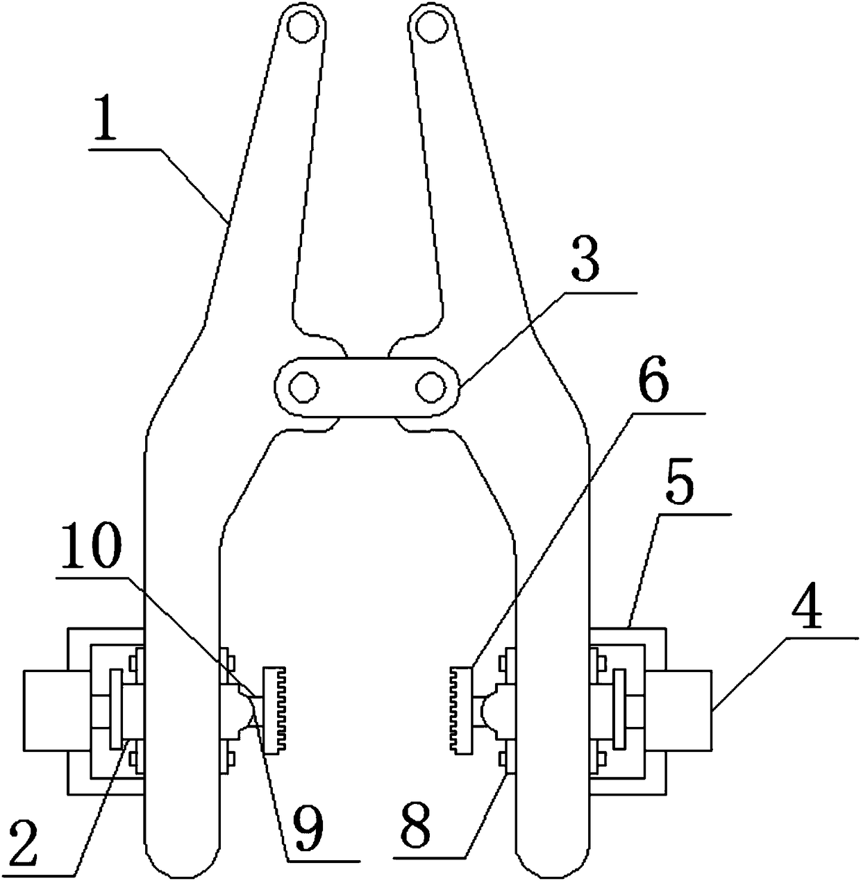
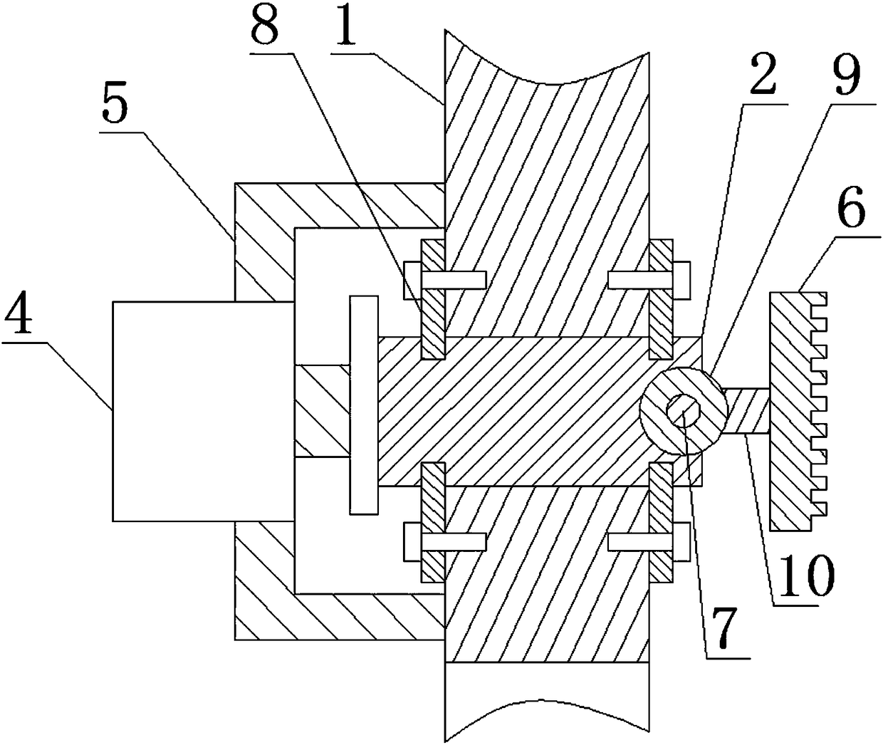
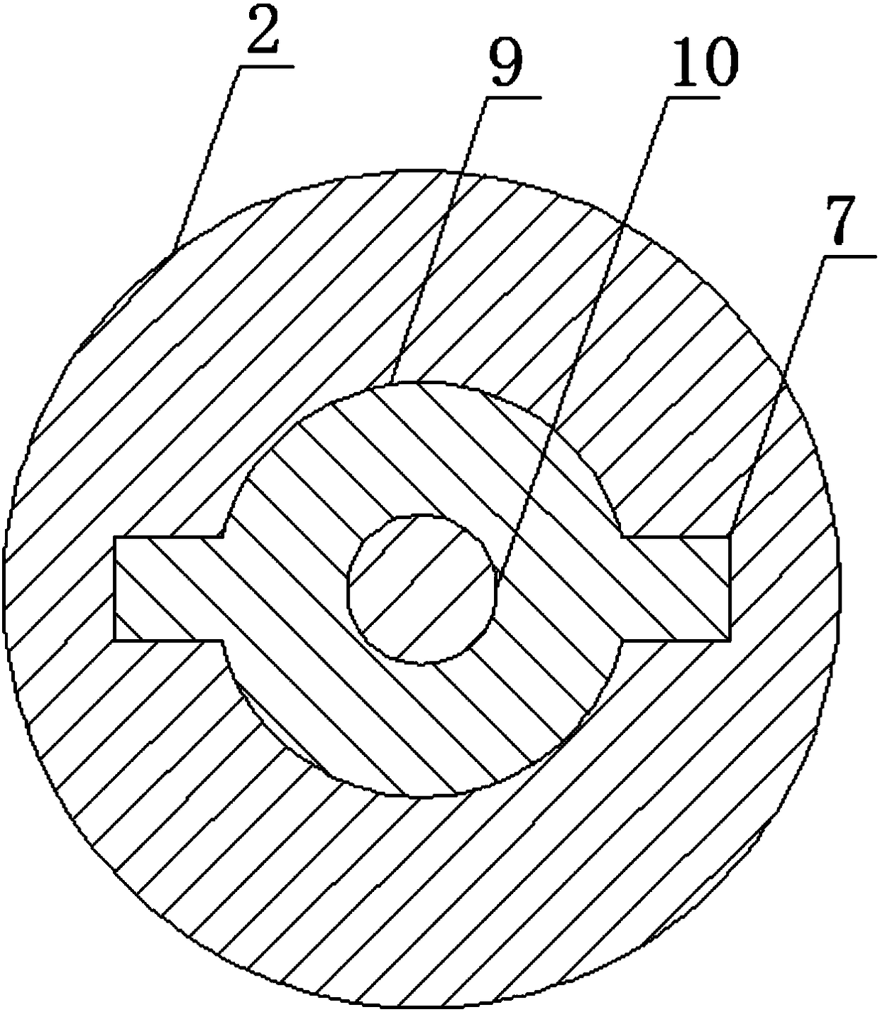
[0016] Such as Figure 1 to Figure 3 As shown, a steel ingot clamping device includes a rotating rod 2 and a pin shaft 3, the two ends of the pin shaft 3 are rotatably connected to the middle part of the pincer rod 1, and the outer side of the pincer rod 1 is fixedly connected to the motor bracket 5, and the motor The middle position of the bracket 5 is fixedly connected with the motor 4, one end of the rotating rod 2 is connected with the motor 4 through a coupling and the other end passes through the pincer rod 1 and is connected with the rotating ball 9, the rotating rod 2 is also provided with a groove and The groove matches the limit plate 8, and the limit plate 8 is fixed on both sides of the clamp rod 3 by bolts, the rotating ball 9 is fixe...


PUM


Abstract

The invention discloses a steel ingot clamping device, and relates to the field of steel ingot equipment. The steel ingot clamping device comprises a rotating rod and a pin shaft, wherein the two endsof the pin shaft are rotationally connected to the middle part of a clamp rod; the outer side of the clamp rod is fixedly connected with a motor support frame; the middle position of the motor support frame is fixedly connected with the motor; one end of the rotating rod is connected with a motor through a shaft coupler; the other end of the rotating rod passes through the clamp rod to be connected with a rotating ball; the other end of a clamp disc rod is fixedly connected with a clamp disc. By using the steel ingot clamping device provided by the invention, during the steel ingot clamping,the rotating ball rolls in the rotating rod, after the steel ingot is clamped, the clamp disc is always in a whole area clamping state; the condition that only the partial clamp disc clamps the steelingot during the clamp since the opening angle of the clamp rod to too big can be avoided, so that the clamping process is stable; when the steel ingot is clamped to a corresponding position, a certain angle is rotated through the motor; the surface shape of the steel ingot facing the placing region is regulated; the placing instability due to the sharp shape of the surface shape of the steel ingot facing the placing region can be avoided.

Description

technical field [0001] The invention relates to the field of steel ingot equipment, in particular to a steel ingot clamping device. Background technique [0002] In the metallurgical industry, steel ingots and billets are the main raw materials for medium and heavy plate production enterprises. When the steel ingots or composite billets from steelmaking are lifted out of the furnace after being heated in the furnace, clamp-type slewing bridge cranes are generally used. The tongs are installed on the bridge crane, and the tongs are conical tooth surfaces. During the hoisting of steel ingots or billets, the clamping surface between the tongs and the steel ingot or billet is small, resulting in cracking of the steel ingot or billet or clamping tooth marks Ultra-deep will affect product quality and reduce product qualification rate. [0003] Chinese patent application number 201720620434.0 discloses a steel ingot tongs lifting tool, which includes tong legs A, tong legs B, pin ...

Claims


Application Information

Patent Timeline
IPC IPC(8): B66C1/44
CPCB66C1/445
Inventor 王军
Owner 马鞍山市鑫龙特钢有限公司
Why Eureka
Try Eureka