An electroplating jig for shielding tip effect

A technology of electroplating fixtures and tip effects, which is applied in the direction of electrolytic components and electrolytic processes, can solve the problems of unsatisfactory coating and thickness, and achieve the effects of saving electroplating time, improving production efficiency, and uniform plating

Active Publication Date: 2020-05-05
AVIC STANDARD PARTS MFG
View PDF13 Cites 0 Cited by
  • Summary
  • Abstract
  • Description
  • Claims
  • Application Information

AI Technical Summary

Problems solved by technology

Usually, when electroplating such products, the electroplating is carried out within the maximum range of 24 hours according to the specified time of the process, but due to the tip effect grabbing the current, the satisfactory coating and thickness are still not obtained in the end, and the pass rate is only about 50%.

Method used


Image

  • An electroplating jig for shielding tip effect
  • An electroplating jig for shielding tip effect
  • An electroplating jig for shielding tip effect

Examples


Embodiment 1

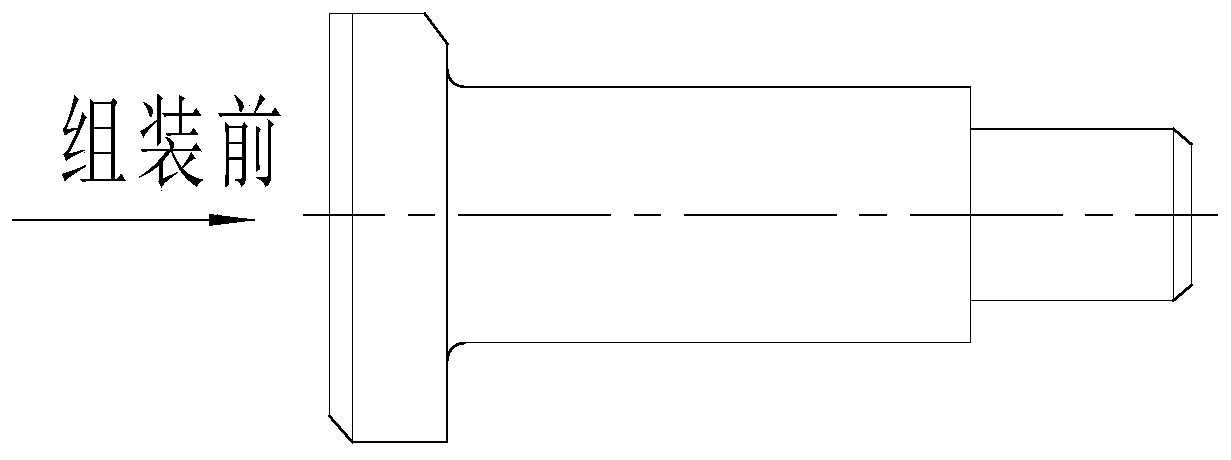
[0013] Partial electroplating is carried out to the bolt whose specification is M5*30, and it is electroplated by using the present invention. Among them, the diameter of the shank of the bolt that needs electroplating is 12MM, and the diameter of the shank that does not need electroplating is 6.5MM, and the length is 15MM.

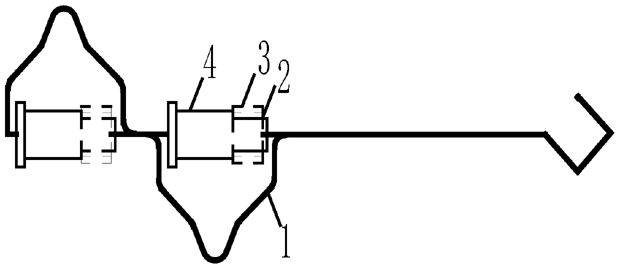
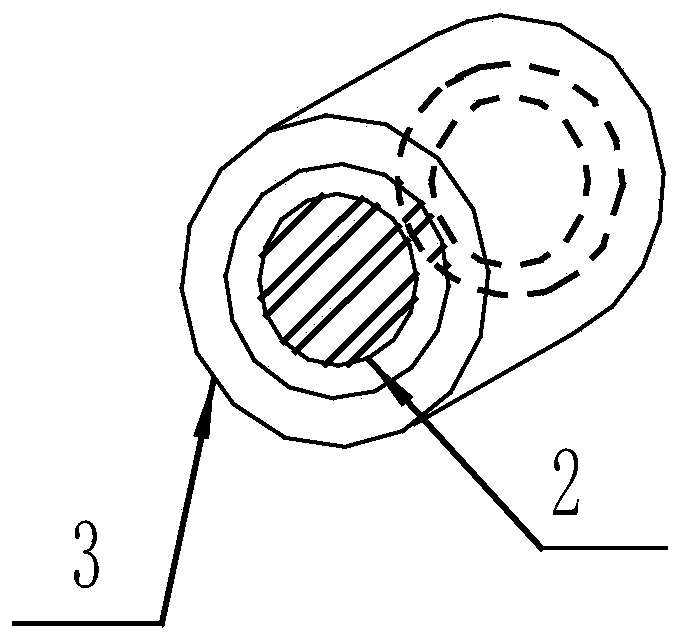
[0014] The electroplating fixture used is composed of an outer ring (3) made of PP material, an insulating inner ring (2) made of thermoplastic tubes, and a copper hook (1). Among them, the entire surface of the copper hook (1) is painted with insulating paint for insulation; the inner diameter of the inner ring (2) of the thermoplastic pipe insulation is 6MM, and the inner diameter of the outer ring (3) made of PP material is 10MM, Their wall thickness is 2MM, and the length is 16-18MM. During use, first put the plastic insulating inner ring (2) on the non-plated rod of the part, then put the outer ring (3) made of non-conductive material on the plastic...

Embodiment 2

[0016] Partial electroplating is carried out on the bolts with the specification of M12×60. The diameter of the shank of the bolt that needs to be electroplated is 23MM, and the diameter of the shank that does not need electroplating is 17.5MM, and the length is 15MM.

[0017] The electroplating fixture used is composed of an outer ring (3) made of PVC material, an insulating inner ring (2) of thermoplastic tubes, and a copper hook (1). Wherein copper hook (1) entire structural surface is brushed with insulating varnish, is insulated; The inner circle diameter of thermoplastic tube insulating inner ring (2) is 18MM, the inner circle diameter of PP material outer ring (3) is 22MM, Their wall thickness is 2MM, and the length is 16-18MM. During use, first put the plastic insulating inner ring (2) on the non-plated rod of the part, then put the outer ring (3) made of non-conductive material on the plastic insulating inner ring (2), and finally put the two ends of the part It is c...


PUM

PropertyMeasurementUnit
diameteraaaaaaaaaa
lengthaaaaaaaaaa
diameteraaaaaaaaaa

Abstract

The invention provides an electroplating clamp capable of preventing a point effect when a fastener is locally electroplated. The electroplating clamp capable of preventing the point effect is mainlycomposed of an outer ring made of non-conducting materials, an insulating inner ring made of plastic, and copper hooks, wherein the whole structural surface of each copper hook is coated with insulating paint for insulation, the excircle diameter of the outer ring made of non-conducting materials is 0.5-2 mm greater than the diameter of the electroplated portion of a part, and the length of the outer ring made of non-conducting materials is smaller than or equal to that of the insulating inner ring made of plastic. When the electroplating clamp is in use, the portion, not to be electroplated,of the part is sleeved with the insulating inner ring made of plastic, then the insulating inner ring made of plastic is sleeved with the outer ring made of non-conducting materials, and finally, thetwo ends of the part are clamped by the copper hooks, so that operation is convenient; and the point portion of the part is shielded by the outer ring made of non-conducting materials, so that the point effect is avoided in the electroplating process, current scrambling of the point end is avoided, and the defects of the prior art are avoided.

Description

Technical field: [0001] The invention relates to a jig, mainly an electroplating jig suitable for avoiding the tip effect when local electroplating of fasteners. Background technique: [0002] The production of fasteners is characterized by small parts and large quantities. In particular, some products require partial plating. For a long time, for products that only require electroplating on the rod, we have used insulating tape and thermoplastic tubes to insulate the head to prevent loosening and falling off. Non-plating parts are insulated with special steel inner ring sleeves. The point negative effect occurs due to the point where the sleeve meets the shank of the part and forms a point face. During the electroplating process, due to the effect of the tip effect, when the electroplating time is only two or three hours, the chromium layer has grown rapidly on the tip surface, and forms dendrites to grow around the end surface. Large, crazily robbed the current, result...

Claims


Application Information

Patent Timeline
Patent Type & Authority Patents(China)
IPC IPC(8): C25D17/08
CPCC25D17/08
Inventor 刘洪郭群徐春红肖文英陈文超王红秀
Owner AVIC STANDARD PARTS MFG
Why Eureka
Try Eureka