Nickel-plated steel strip, steel battery case manufactured from the steel strip, and method of manufacturing the steel battery case

A battery steel shell and steel strip technology, applied in battery pack parts, circuits, electrical components, etc., can solve the problems of affecting battery storage life, rusting on the outer surface of the battery, and increasing the porosity of the coating, so as to avoid battery leakage. problem, improve the leakage problem, improve the effect of bonding force

Pending Publication Date: 2019-02-01
宁波堇山新材料有限公司
View PDF0 Cites 3 Cited by
  • Summary
  • Abstract
  • Description
  • Claims
  • Application Information

AI Technical Summary

Problems solved by technology

[0007] (1) High material cost
Since the nickel is evenly plated on the steel strip, there is also nickel of the same thickness on the leftover material produced when punching the steel shell, resulting in a relatively large loss and waste of nickel;
[0008] (2) Alkaline batteries are prone to leakage when using this process for long-term storage
The nickel layer on the surface of the pre-nickel-plated steel strip is also continuously stretched and deformed during the stretching and punching process of the steel shell. During the stretching deformation process, cracks and defective points in the coating will be continuously stretched and enlarged, forming a large number of The cracks that go straight to the substrate, after the battery is stored for a long time, the iron components on the steel strip substrate under these cracks will gradually dissolve and cause battery leakage, affecting the storage life of the battery;
[0009] (3) The cracks through the substrate produced by the steel shell during the stretching and punching process are likely to cause rust on the outer surface of the battery
[0012] (1) Limited by the deep plating capacity of the deep hole electroplating process, the thickness of the nickel coating on the inner surface of the steel is insufficient. Usually, the nickel coating on the inner bottom of the steel shell can only reach about 0.25, which is difficult to increase, because even through various The method increases the thickness (for example, some manufacturers have plated to 0.35 microns), the porosity in the coating will increase greatly, the storage life of the battery will be shortened rapidly, and even leakage will occur in one or two years.
Since the nickel coating on the surface of the steel shell produced by the post-electroplating process is relatively thin, the storage electrical performance of the battery is relatively poor, and the electrical performance of the battery will decline more than that of the battery of the pre-nickeling process after storage for a certain period of time (such as more than half a year). About 5%;
[0013] (2) Limited by the deep hole electroplating process, the electroplating speed of the outer surface of the steel shell is much greater than that of the inner surface. In order to increase the thickness of the inner surface coating as much as possible, the thickness of the outer surface coating must be increased synchronously, resulting in steel shell The thickness of the coating on the outer surface is much higher than the thickness required for normal anti-corrosion outside the steel shell, resulting in the waste of expensive nickel metal and the increase of electroplating costs
For example, for the LR6 steel shell, when the thickness of the coating at the bottom of the inner surface reaches 0.25 microns, the thickness of the coating at the head of the steel shell reaches an average of more than 3.5 microns, and the thickest part even exceeds 5 microns, while the nickel coating on the outer surface plays a major role It is anti-rust, usually 2 microns is enough, which causes a waste of nickel consumption and increases the cost of electroplating;
[0014] (3) Although the nickel coating of the post-electroplating process no longer needs stretching and processing, theoretically speaking, the compactness of the electroplating layer is relatively good, but due to the need to add a large amount of electroplating additives for deep hole electroplating, problems such as electroplating process and production process management It will seriously affect the quality of the coating. Once the process design is unreasonable or the control of the plating bath solution fluctuates, the capacity will cause problems such as a substantial increase in the porosity of the coating. In severe cases, the porosity will be higher than that of steel produced by the pre-nickeling process. Shell, the storage life of the battery will even be lower than the pre-nickeling process;
[0015] (4) There is a certain amount of sulfur in the coating of the post-plating process, which is the product of the decomposition of electroplating additives. The existence of sulfur in the coating will affect the corrosion resistance of the coating, and the coating will gradually turn yellow in a few months. Oxidation, at the same time affects the conductivity, causing false power shortages when the battery is in use;
[0016] (5) The nickel flower at the cut is likely to cause nickel powder problems, and it is easy to cause leakage after being mixed into the battery
[0017] There is also a more realistic problem in the post-plating process: with the strengthening of the government's environmental protection efforts, decentralized steel shell electroplating manufacturers are increasingly feeling the pressure of environmental protection, and the cost of electroplating is getting higher and higher. How to improve the production efficiency of electroplating It has also become a key issue for them to consider

Method used


Image

  • Nickel-plated steel strip, steel battery case manufactured from the steel strip, and method of manufacturing the steel battery case
  • Nickel-plated steel strip, steel battery case manufactured from the steel strip, and method of manufacturing the steel battery case
  • Nickel-plated steel strip, steel battery case manufactured from the steel strip, and method of manufacturing the steel battery case

Examples


Embodiment 1

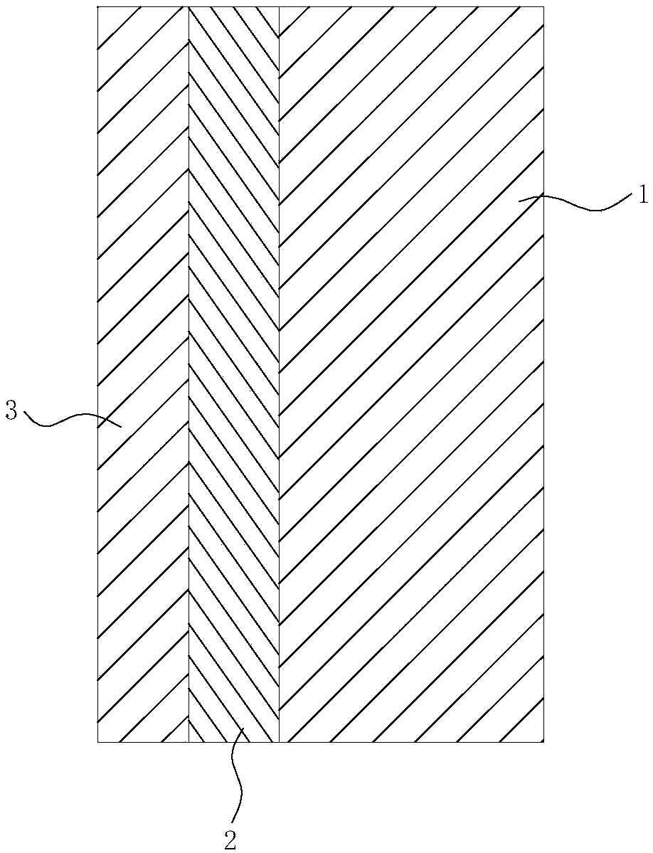
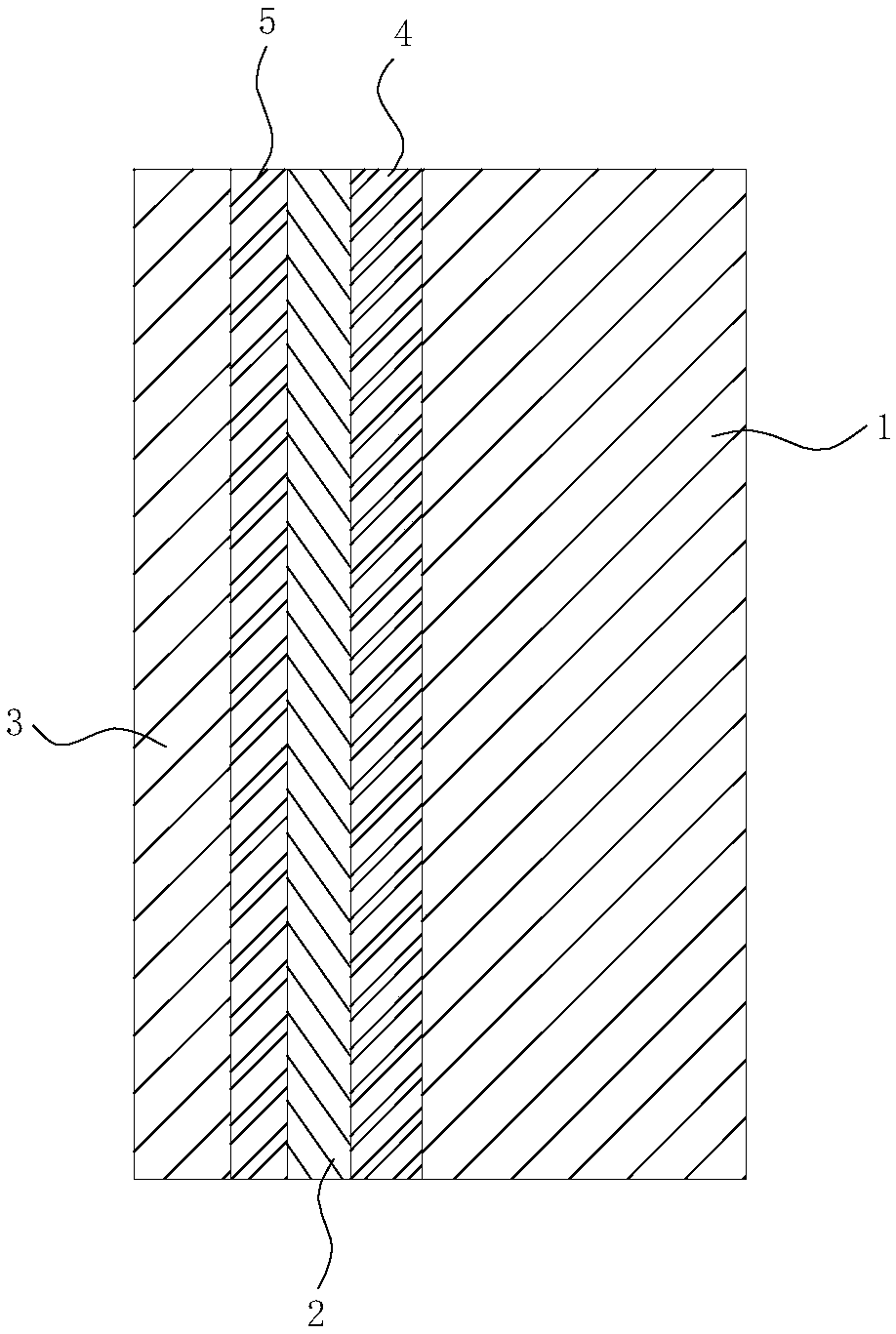
[0061] Such as figure 1 , 2 As shown, the Ni-coated steel strip in this embodiment includes an Fe substrate 1 , the inner surface of the Fe substrate 1 has a Ni coating 2 , and the surface of the Ni coating 2 has an Fe coating 3 . Under the effect of heat treatment, the part of the Ni coating 2 close to the Fe matrix 1 interpenetrates and alloys with the Fe matrix 1 to form the bottom Fe-Ni alloy layer 4, and the Fe coating 3 and the Ni coating 2 interpenetrate and alloy to form the surface Fe-Ni alloy Layer 5, a part of Ni plating layer 2 remains between the surface Fe-Ni alloy layer 5 and the bottom Fe-Ni alloy layer 4.

[0062] In the present embodiment, the surface of the Fe substrate and the Ni coating are not interpenetrated and alloyed, the thickness of the Ni coating 2 is 0.3 μm, the thickness of the Fe coating 3 on the surface of the Ni coating 2 is 0.015 μm, and the surface of the Fe substrate 1 and the Ni coating 2 In the state where the bottom Fe-Ni alloy layer 4...

Embodiment 2

[0074] Such as figure 1 , 2 As shown, the Ni-coated steel strip in this embodiment includes an Fe substrate 1 , the inner surface of the Fe substrate 1 has a Ni coating 2 , and the surface of the Ni coating 2 has an Fe coating 3 . Under the effect of heat treatment, the part of the Ni coating 2 close to the Fe matrix 1 interpenetrates and alloys with the Fe matrix 1 to form the bottom Fe-Ni alloy layer 4, and the Fe coating 3 and the Ni coating 2 interpenetrate and alloy to form the surface Fe-Ni alloy Layer 5, a part of Ni plating layer 2 remains between the surface Fe-Ni alloy layer 5 and the bottom Fe-Ni alloy layer 4.

[0075] In the present embodiment, the surface of the Fe substrate and the Ni coating are not interpenetrated and alloyed, the thickness of the Ni coating 2 is 1.0 μm, the thickness of the Fe coating 3 on the surface of the Ni coating 2 is 0.02 μm, and the surface of the Fe substrate 1 and the Ni coating 2 In the state where the bottom Fe-Ni alloy layer 4 ...

Embodiment 3

[0087] Such as figure 1 , 2 As shown, the Ni-coated steel strip in this embodiment includes an Fe substrate 1 , the inner surface of the Fe substrate 1 has a Ni coating 2 , and the surface of the Ni coating 2 has an Fe coating 3 . Under the effect of heat treatment, the part of the Ni coating 2 close to the Fe matrix 1 interpenetrates and alloys with the Fe matrix 1 to form the bottom Fe-Ni alloy layer 4, and the Fe coating 3 and the Ni coating 2 interpenetrate and alloy to form the surface Fe-Ni alloy Layer 5, a part of Ni plating layer 2 remains between the surface Fe-Ni alloy layer 5 and the bottom Fe-Ni alloy layer 4.

[0088] In this embodiment, when the surface of the Fe substrate is not interpenetrated and alloyed with the Ni coating, the thickness of the Ni coating 2 is 0.7 μm, and the surface of the Fe substrate 1 and the Ni coating 2 are interpenetrated and alloyed to form the bottom Fe-Ni alloy layer 4. , the thickness of the underlying Fe-Ni alloy layer 4 is about ...


PUM

PropertyMeasurementUnit
thicknessaaaaaaaaaa
thicknessaaaaaaaaaa
thicknessaaaaaaaaaa

Abstract

The invention relates to a nickel-plated steel strip, a steel battery case manufactured from the steel strip, and a method of manufacturing the steel battery case. In the invention, firstly, a pre-nickel-plating layer is formed on the inner surface of the steel strip; then through thermal treatment, a surface layer and a bottom Fe-Ni alloy layer are formed from the inter-permeated pre-nickel-plating layer and a contact surface, a part of the nickel-plating layer being reserved between the surface layer and the bottom Fe-Ni alloy layer, so that a problem that on the steel strip, during a steelcase stamping process, cracks are liable to generate in the plating layer is avoided; the surface layer and the bottom Fe-Ni alloy layer formed through the thermal treatment have compact structure, sothat not only is excellent anticorrosive performance achieved, but also the combining force between the Fe-Ni alloy layer and the Fe substrate is far higher than that between the plating layer and the Fe substrate in the prior art, so that by improving the combining force between the plating layer and the Fe substrate, the problem of forming cracks in the plating layer during the steel case stamping process is greatly solved, thus solving liquid leakage during long time storage of the battery. In addition, a part of the nickel-plating layer is reserved, thus preventing iron from dissolving out from the Fe-Ni alloy layer.

Description

technical field [0001] The invention relates to the technical field of steel strips and steel cases for batteries, in particular to a Ni-plated steel strip, a battery steel case using the steel strip, and a preparation method for the steel case. Background technique [0002] The steel case for batteries adopts the process of nickel-plating on the surface of the iron substrate, and the nickel-plating process is usually divided into two processes: pre-nickel plating and post-plating. [0003] Foreign battery manufacturers mainly use pre-nickel plating process. This process is to first nickel-plate the surface of the steel strip, the raw material of the steel shell, to become a pre-nickel-plated steel strip, and then stretch and punch it to form a steel shell. The pre-nickel plating process has the following advantages: [0004] (1) Since pre-plating is to electroplate the raw material steel strip of the steel shell earlier, the thickness of the electroplating layer on the su...

Claims


Application Information

Patent Timeline
Patent Type & Authority Applications(China)
IPC IPC(8): H01M2/02C25D5/12C25D7/06H01M50/124
CPCC25D5/12C25D7/0614H01M50/124H01M50/1245Y02E60/10
Inventor 忻锋光
Owner 宁波堇山新材料有限公司
Why Eureka
Try Eureka