A method for manufacturing transparent electric heating glass with high light transmittance and low square resistance

An electric heating glass, high light transmittance technology, applied in transparent/reflective heating devices, printed circuit manufacturing, copying/marking methods, etc. Effect

Active Publication Date: 2021-06-25
QINGDAO TECHNOLOGICAL UNIVERSITY
View PDF7 Cites 0 Cited by
  • Summary
  • Abstract
  • Description
  • Claims
  • Application Information

AI Technical Summary

Problems solved by technology

[0008] To sum up, among the current manufacturing technologies of transparent electric heating glass, it is difficult to achieve low square resistance (less than 1Ω / sq), high light transmittance (greater than 90%), and high adhesion (greater than 80N) heating wire at low cost. Manufacturing, it is urgent to develop new technologies to achieve low-cost, mass-produced high-performance electric heating glass with heating line light transmittance greater than 90%, square resistance less than 1Ω / sq, and adhesion greater than 80N

Method used


Image

  • A method for manufacturing transparent electric heating glass with high light transmittance and low square resistance
  • A method for manufacturing transparent electric heating glass with high light transmittance and low square resistance
  • A method for manufacturing transparent electric heating glass with high light transmittance and low square resistance

Examples


Embodiment 1

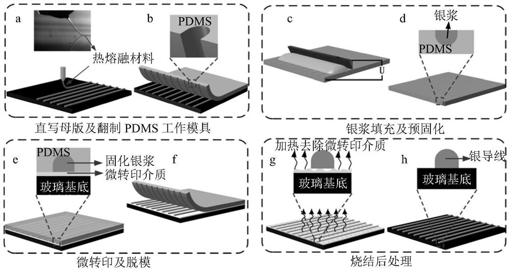
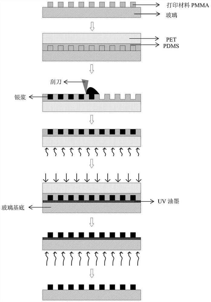
[0071] In this embodiment, a large-area master mold structure is manufactured by electric field-driven fused deposition direct writing technology, and then the master mold structure is transferred to the PDMS working mold through a graphic replication process, and then the PDMS working mold is filled with high-temperature sintered silver paste, and finally the PDMS working mold is filled with UV-assisted microtransfer transfers the conductive structure to the target substrate (glass), and the fabricated pattern structure is a wire grid structure. manufacturing process such as figure 2 As shown, the specific preparation steps include:

[0072] (1) Manufacture of the master mold: a large-size master mold (master plate) is manufactured using the electric field-driven fused deposition direct writing technology.

[0073] Ordinary glass is used as the substrate (substrate). Firstly, the glass substrate was cleaned, deionized water was ultrasonically treated for 10 minutes, and th...

Embodiment 2

[0090] In this embodiment, a large-area master mold structure is manufactured by electric field-driven fused deposition direct writing technology, and then the master mold structure is transferred to PDMS through a pattern replication process, and then the PDMS working mold is filled with high-temperature sintered silver paste, and finally UV-assisted Micro-transfer printing transfers the silver wires to the target substrate (glass), and the fabricated conductive structure is a grid structure. manufacturing process such as figure 2 As shown, the specific preparation steps include:

[0091] (1) Manufacture of the master mold: a large-size master mold (master plate) is manufactured using the electric field-driven fused deposition direct writing technology.

[0092] Ordinary glass is used as the substrate (substrate). Firstly, the glass substrate was cleaned, ultrasonically treated with deionized water for 10 min, and then blown dry with nitrogen. Using PMMA as the printing m...


PUM

PropertyMeasurementUnit
thicknessaaaaaaaaaa
diameteraaaaaaaaaa
adhesivityaaaaaaaaaa

Abstract

The invention relates to a method for manufacturing transparent electric heating glass with high light transmittance and low square resistance, which combines electric field-driven fused deposition direct writing and UV-assisted micro-transfer to achieve high aspect ratio (0.7-2) and high resolution ( 1‑20 micron) heating wire of transparent electric heating glass for low cost and mass production. The method combines the advantages of electric field-driven fused deposition direct writing and UV-assisted micro-transfer technology, and has the outstanding features and significant advantages of simple process, low manufacturing cost, high production efficiency, good consistency, especially the ability to achieve high transparency Low cost and mass production of transparent electrically heated glass with light rate (greater than 90%) and low square resistance (less than 1Ω / sq). This provides a new solution for low-cost and large-scale manufacturing of large-area, high-performance transparent electrically heated glass.

Description

technical field [0001] The invention belongs to the technical field of transparent electric heating glass manufacturing, and specifically relates to a low-cost and mass-produced transparent electric heating glass that combines electric field-driven fused deposition direct writing and UV-assisted micro-transfer printing technology to achieve high light transmittance and low square resistance Methods. Background technique [0002] Transparent electrically heated glass has a very wide range of applications in many fields and products, and plays an extremely important role in defogging, defrosting and anti-icing in the fields of automobiles, aircraft, construction, display, and military. Especially in cold and humid countries and regions, the application requirements are more prominent and obvious. However, the manufacturing technology of electric heating glass at this stage is difficult to balance the low square resistance and high light transmission characteristics of electri...

Claims


Application Information

Patent Timeline
Patent Type & Authority Patents(China)
IPC IPC(8): H05K3/12H05K3/18H05B3/84B41M5/00B41M7/00
CPCB41M5/007B41M7/00H05B3/84H05K3/1275H05K3/1283H05K3/18
Inventor 朱晓阳许权李红珂兰红波杨建军彭子龙王飞
Owner QINGDAO TECHNOLOGICAL UNIVERSITY
Why Eureka
Try Eureka