
Process for forming pipe end sleeves

A forming process and parts technology, which is applied in the field of forming process of pipe end sleeve parts, can solve the problems of non-sticking tires, increased forming work, and the inability of manual forming to ensure that parts fully meet the requirements of drawings, etc.

Inactive Publication Date: 2017-02-15
HARBIN
View PDF13 Cites 0 Cited by
  • Summary
  • Abstract
  • Description
  • Claims
  • Application Information

AI Technical Summary

Problems solved by technology

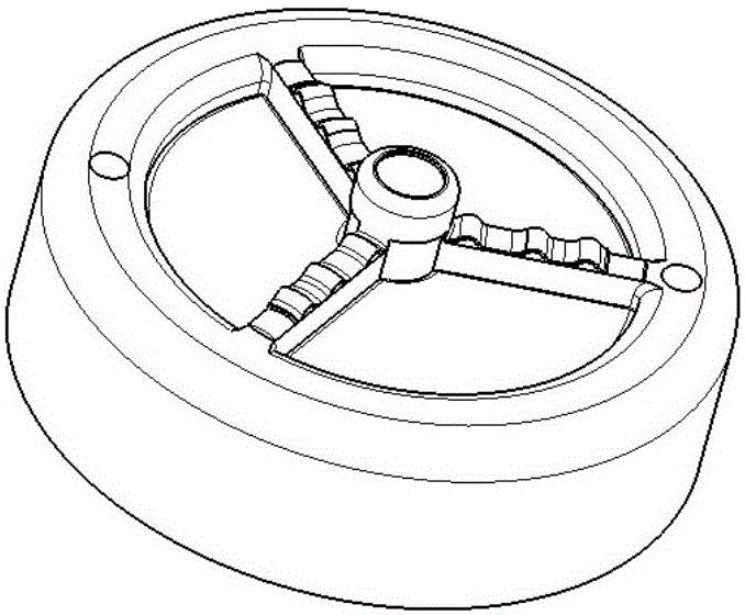
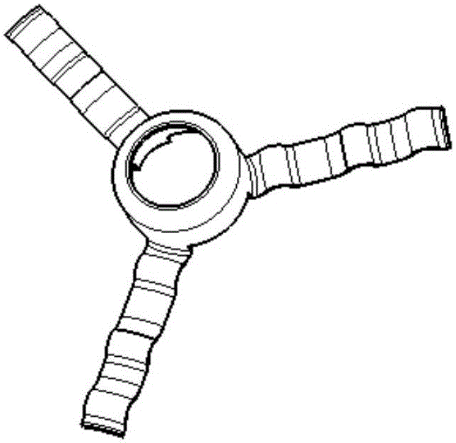
[0002] In the research and production process of a certain type of machine, the shape of the parts is as follows: Figure 1 , The material of this kind of pipe end sleeve parts is LF21M aluminum plate of GBn168-82, the thickness of the material is 0.6mm, the size of the part is 250mm×250mm, the height of the three small claws of the part is 35mm, and each small claw has The wavy bending and small claws add great difficulty to the operator's forming work, which is prone to non-stick tires and insufficient corrugation depth. Manual forming cannot ensure that the parts fully meet the requirements of the drawing, and the parts will Figure II The three small claws of the Figure 1 Defects such as cracks are prone to appear in the shape process

Method used


Image

  • Process for forming pipe end sleeves
  • Process for forming pipe end sleeves
  • Process for forming pipe end sleeves

Examples


Embodiment Construction

[0020] to attach figure 1 Take the part shown as an example to explain the forming process of the part in detail:

[0021] (1) The shearing machine is used for cutting the material, and the rectangular wool is cut by the shearing machine.

[0022] (2) Stamping and blanking, firstly, the workers use the punch 63T to drop the circular unfolded material to prepare for spinning.

[0023] (3) Spinning forming, sheet metal operators use spinning tires to form parts, the effect is as follows Figure three .

[0024] (4) Stamping and punching, first the worker drills the tool hole, and then uses the punching machine to punch the hole.

[0025] (5) Sheet metal forming. First, workers use the mold to cut and shape. The cutting and forming mold only has the cutting function. When cutting, put the spinning-formed hat on the lower mold, and then use this set of molds to cut. This process scheme can effectively avoid the occurrence of stress concentration when forming small flanges.

...


PUM


Abstract

The invention belongs to the field of forming processes of complicated metal plate parts, and relates to a process for forming pipe end sleeves. By adoption of the forming method, the problems that three tiny paws are not attached to a mould and roots of the tiny paws are prone to cracking are solved, the edge-bending forming difficulty of the parts is greatly lowered, the labor amount of operators is decreased, the production efficiency is improved, the rejection rate of the parts is lowered to 1%-5%, and the production cost is reduced. According to the novel technical scheme, a great progress is made both in the aspect of the economic benefits and in the aspect of quality.

Description

technical field [0001] The invention belongs to the category of forming technology of sheet metal complex parts, and relates to a forming technology method of pipe end sleeve parts. Background technique [0002] In the research and production process of a certain type of machine, the shape of the parts is as follows: Figure 1 , The material of this kind of pipe end sleeve parts is LF21M aluminum plate of GBn168-82, the thickness of the material is 0.6mm, the size of the part is 250mm×250mm, the height of the three small claws of the part is 35mm, and each small claw has The wavy bending and small claws add great difficulty to the operator's forming work, which is prone to non-stick tires and insufficient corrugation depth. Manual forming cannot ensure that the parts fully meet the requirements of the drawing, and the parts will Figure II The three small claws of the Figure 1 Defects such as cracks are prone to appear during the shape process. Contents of the invention ...

Claims


Application Information

Patent Timeline
Patent Type & Authority Applications(China)
IPC IPC(8): B23P15/00B21D35/00
CPCB23P15/00B21D35/002
Inventor 王鹤
Owner HARBIN
Learn More