Cloth clipping and conveying device for textile processing

A conveying device and fabric conveying technology, which is applied in the cutting, transportation and packaging of textile materials, textiles and paper making, etc.

Inactive Publication Date: 2018-06-29
佛山市冠康隆纺织有限公司
View PDF0 Cites 19 Cited by
  • Summary
  • Abstract
  • Description
  • Claims
  • Application Information

AI Technical Summary

Problems solved by technology

[0004] The purpose of the present invention is to provide a cloth cutting and conveying device for textile processing, which can effectively solve the problem that the cloth conveying device in the prior art cannot ensure the smoothness of the cloth during the conveying process and the cutting quality is difficult to guarantee when conveying the cloth ; The interior of the present invention is equipped with a cloth conveying mechanism and a lifting pressure roller mechanism, which can effectively clamp and convey the cloth, and the distance between the cloth conveying mechanism and the lifting pressure roller mechanism can be adjusted, which is convenient to be suitable for use without Thickness of the cloth for conveying or suitable for multi-layer cloth synchronous conveying and cutting processing

Method used


Image

  • Cloth clipping and conveying device for textile processing
  • Cloth clipping and conveying device for textile processing
  • Cloth clipping and conveying device for textile processing

Examples


specific Embodiment approach 1

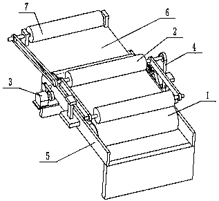
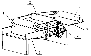
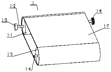
[0029] Such as Figure 1-11As shown, a cloth cutting and conveying device for textile processing includes a cloth conveying mechanism 1, a lifting and lowering cloth roller mechanism 2, a driving mechanism 3, a tensioning transmission mechanism 4, a frame 5, a cutting table 6 and a cloth delivery roller mechanism 7 , the cloth conveying mechanism 1 is connected to the inner side of the frame 5; the lifting press roller mechanism 2 is arranged on the upper end of the cloth conveying mechanism 1, and both sides of the bottom end of the lifting press roller mechanism 2 are respectively connected to the frame 5 in the middle of both ends; the drive mechanism 3 is fixedly connected to the left end of the frame 5, and the drive mechanism 3 is connected to the cloth conveying mechanism 1; the tension transmission mechanism 4 is fixedly connected to the right end of the frame 5, and the cloth conveying mechanism 1 passes through The tension transmission mechanism 4 is connected to the...


PUM


Abstract

The invention relates to the field of textile processing and particularly relates to a cloth clipping and conveying device for textile processing. The cloth clipping and conveying device comprises a cloth conveying mechanism, a cloth pressing roll lifting mechanism, a driving mechanism, a tension transmission mechanism, a stander, a clipping table and a cloth discharging roll mechanism, wherein the cloth conveying mechanism is connected to the inner side of the stander; the cloth pressing roll lifting mechanism is arranged at the upper end of the cloth conveying mechanism, and two sides of thebottom end of the cloth pressing roll lifting mechanism are respectively connected to the middles of two ends of the stander; the driving mechanism is fixedly connected to the left end of the standerand is connected with the cloth conveying mechanism; and the tension transmission mechanism is fixedly connected to the right end of the stander, and the cloth conveying mechanism is connected to thecloth pressing roll lifting mechanism through the tension transmission mechanism. According to the invention, the cloth conveying mechanism and the cloth pressing roll lifting mechanism are arrangedin the cloth clipping and conveying device, so that the cloth can be clamped and conveyed effectively, and the distance between the cloth conveying mechanism and the cloth pressing roll lifting mechanism can be adjusted, so as to be suitable for conveying cloth of different thickness.

Description

technical field [0001] The invention relates to the field of textile processing, in particular to a cloth cutting and conveying device for textile processing. Background technique [0002] Cloth is a commonly used material in decorative materials. Including chemical fiber carpets, non-woven wall coverings, linen cloth, nylon cloth, colored tape, flannel and other fabrics. Cloth plays a considerable role in the decorative display, and is often the main force that cannot be ignored in the entire sales space. Extensive use of fabrics for wall decoration, partitions, and background treatment can also form a good commercial space display style. From the weaving method, it can be divided into two categories: woven fabric and knitted fabric. From the processing technology, it can be divided into: gray cloth, bleached cloth, dyed cloth, printed cloth, yarn-dyed cloth, mixed process cloth (such as printing on yarn-dyed cloth, composite cloth, flocking cloth, faux fur cloth) and so...

Claims


Application Information

Patent Timeline
Patent Type & Authority Applications(China)
IPC IPC(8): D06H7/00B65H35/00
CPCD06H7/00B65H35/00
Inventor 冼瑞辉
Owner 佛山市冠康隆纺织有限公司
Why Eureka
Try Eureka