Centering mold device for assembled grouting bushing of concrete structure

A technology for concrete structures and grouting sleeves, which is applied in building construction, construction, and building materials processing, etc., can solve the problems of reducing the effectiveness of steel grouting connection work, reducing the uniformity of grouting work, and reducing grouting work efficiency. The effect of improving convenience and efficiency, improving convenience, improving efficiency and effectiveness

Inactive Publication Date: 2018-06-29
诸暨市开翎工业设计有限公司
View PDF0 Cites 6 Cited by
  • Summary
  • Abstract
  • Description
  • Claims
  • Application Information

AI Technical Summary

Problems solved by technology

[0006] Aiming at the deficiencies of the prior art, the present invention provides an assembled concrete structure grouting sleeve centering mold device, which has a fixed structure for centering the grouting sleeve and high strength, and performs rotary grouting work, effectively improving the The uniformity of the grouting work and the grouting efficiency solve the problem that the common grouting sleeve has a simple structure and is mainly composed of a sleeve, a grouting inlet and a grouting outlet, because there is no effective centering and fixing of the steel bars to be connected. structure, during the grouting work, it is very easy to cause the offset of the steel bar, which brings inconvenience to the normal grouting work, and greatly reduces the effectiveness of the steel bar grouting connection work. The rotating structure greatly reduces the uniformity of the grouting work while reducing the grouting work efficiency

Method used


Image

  • Centering mold device for assembled grouting bushing of concrete structure
  • Centering mold device for assembled grouting bushing of concrete structure
  • Centering mold device for assembled grouting bushing of concrete structure

Examples


Embodiment Construction

[0030] The following will clearly and completely describe the technical solutions in the embodiments of the present invention with reference to the accompanying drawings in the embodiments of the present invention. Obviously, the described embodiments are only some, not all, embodiments of the present invention. Based on the embodiments of the present invention, all other embodiments obtained by persons of ordinary skill in the art without making creative efforts belong to the protection scope of the present invention.

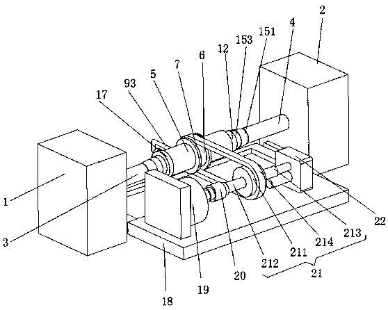
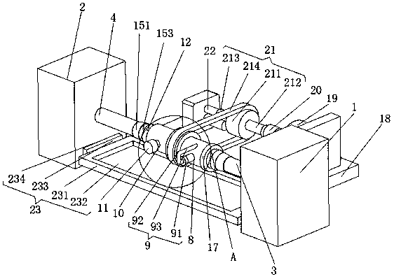
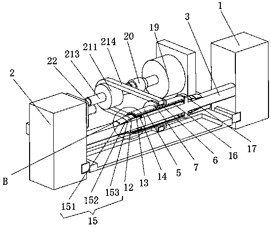
[0031] see Figure 1-5, a prefabricated concrete structure grouting sleeve centering mold device, comprising a beam left end 1 and a beam right end 2, a left steel bar 3 is fixedly installed in the middle inside the beam left end 1, and a right steel bar 4 is fixedly installed in the middle inside the beam right end 2, The outer movable sleeve of the left steel bar 3 and the opposite surface of the right steel bar 4 is connected with a sleeve body 5, and the o...


PUM


Abstract

The invention relates to the technical field of grouting equipment and discloses a centering mold device for an assembled grouting bushing of a concrete structure. The mold comprises a beam left end and a beam right end, wherein a left reinforcing steel rib is fixedly mounted in the middle of the inner side of the beam left end, a right reinforcing steel rib is fixedly mounted in the middle of theinner side of the beam right end, a bushing body is movably connected to the outer side of the opposite surfaces of the left and right reinforcing steel ribs in a sleeving manner, and a fixed sleevedisc is fixedly connected to the outer side of the middle of the bushing body in a sleeving manner. According to the centering mold device for the assembled grouting bushing of the concrete structure,a rotating transmission belt drives the sleeve body to rotate by means of the fixed sleeve disc, so that slurry enters the outer side of the reinforcing steel rib through a slurry outlet hole in themiddle of a filter pulp bushing, so that the uniformity of pouring the slurry in the grouting work is improved effectively; meanwhile, by combining the connecting bushing, an external threaded connection strip and an internal threaded connection strip, the transmission belt has a detachable function, so that the practicality of the grouting device is further improved.

Description

technical field [0001] The invention relates to the technical field of grouting equipment, in particular to an assembled concrete structure grouting sleeve centering mold device. Background technique [0002] The grouting sleeve is a combination of specially processed sleeves, matching grouting materials and steel bars. When connecting the steel bars, the fast-hardening non-shrinking grouting material is injected, and the steel bar and the sleeve are connected by the bonding and occlusion between the materials. The grouting joint has the advantages of reliable performance, wide applicability, and easy installation. [0003] The grouting sleeve connection technology is suitable for reinforced concrete structure engineering, steel structure engineering, bridge engineering, offshore oil exploration platform engineering and offshore wind power towers. The emergence of this new steel structure connection method makes up for the shortcomings of the traditional steel structure con...

Claims


Application Information

Patent Timeline
Patent Type & Authority Applications(China)
IPC IPC(8): E04G21/02E04G21/12
CPCE04G21/185E04G21/122
Inventor 李亮
Owner 诸暨市开翎工业设计有限公司
Why Eureka
Try Eureka