High-efficiency heat dissipating device

A heat dissipation device and high-efficiency technology, which is applied in the direction of lighting devices, cooling/heating devices of lighting devices, lighting and heating equipment, etc., can solve the problems of only one direction of air convection and unsatisfactory heat dissipation effect, and achieve simple structure, Good air convection and improved heat dissipation

Inactive Publication Date: 2018-06-29
江健良
View PDF0 Cites 0 Cited by
  • Summary
  • Abstract
  • Description
  • Claims
  • Application Information

AI Technical Summary

Problems solved by technology

The existing radiator, as shown in Figure 5-6, generally can only transfer the heat generated by the semiconductor device from the upper part of the radiator to the lower part of the radiator, and at the same time transfer heat from the center of the radiator to the heat transfer fins on the outer wall of the radiator. Air convection can only be in one direction, and the heat dissipation effect is not ideal

Method used


Image

  • High-efficiency heat dissipating device
  • High-efficiency heat dissipating device
  • High-efficiency heat dissipating device

Examples


Embodiment Construction

[0018] The present invention will be further described below in conjunction with accompanying drawing description and specific embodiment:

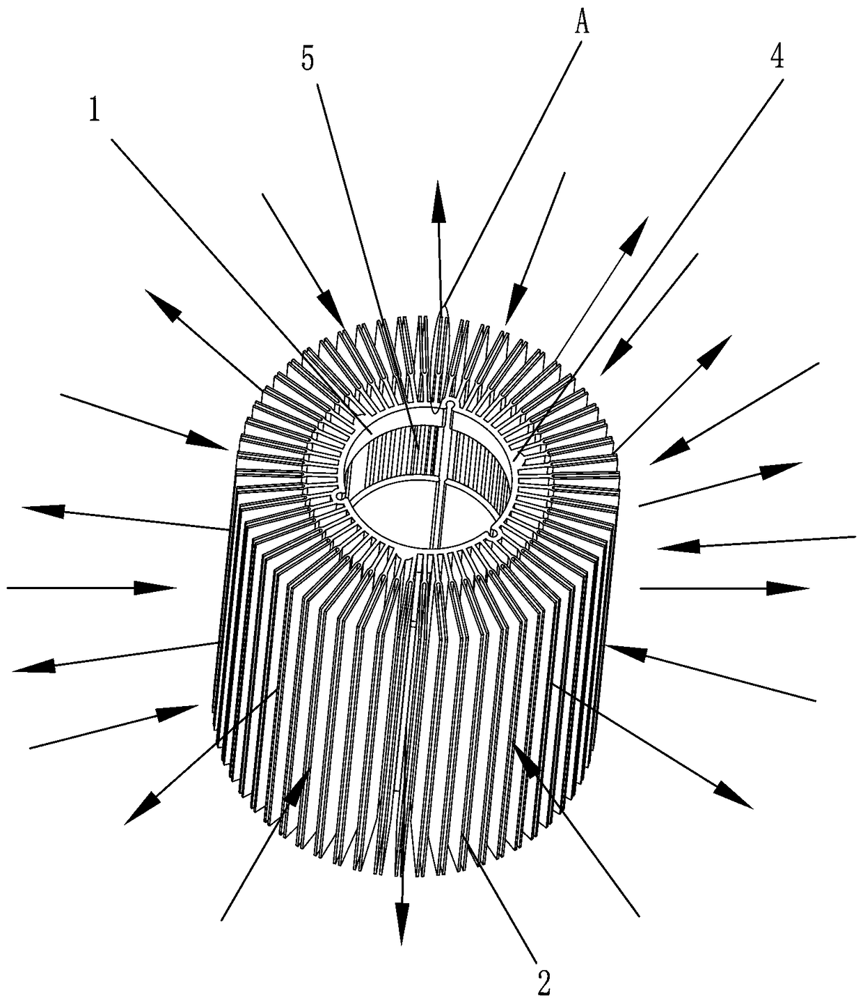
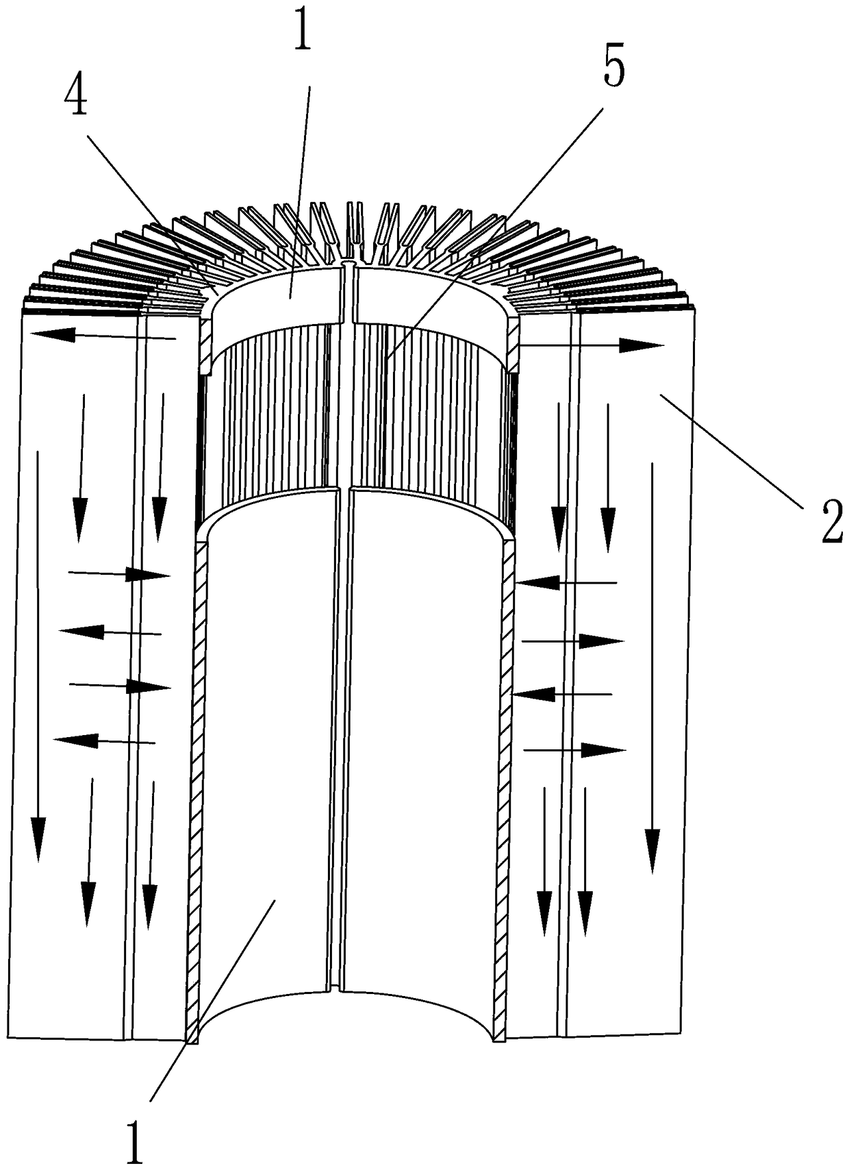
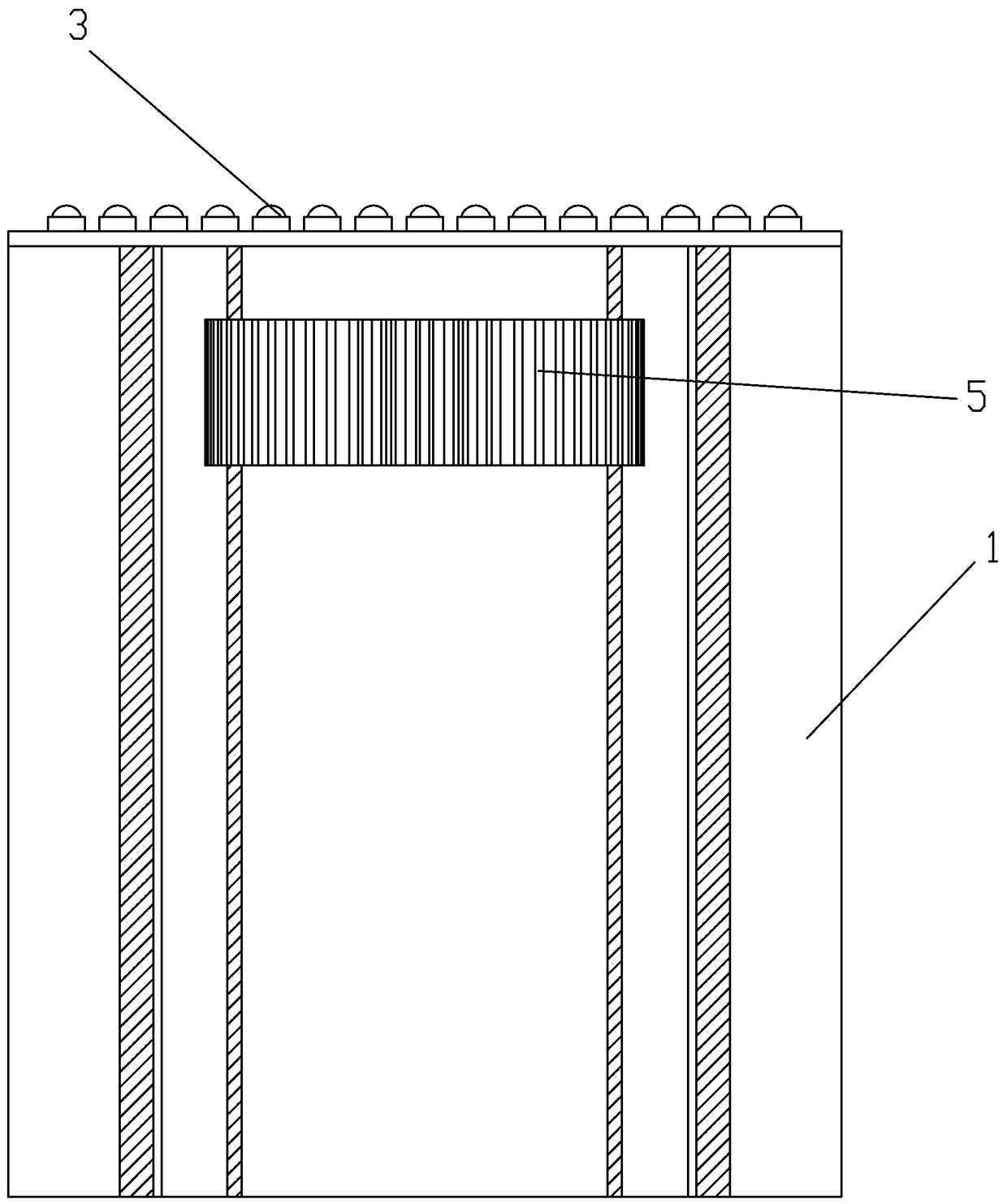
[0019] A high-efficiency heat dissipation device as shown in Figures 1 to 4 includes a central heat dissipation column 1, a plurality of heat transfer fins 2 are arranged on the central heat dissipation column 1, and a useful On the plane 4 where the semiconductor device 3 is installed, a heat-resisting pit is provided on the upper end of the central cooling column 1 to drive the heat generated by the semiconductor device 3 to the heat transfer sheet 2 first.

[0020] The central cooling column 1 in the present invention is a cylindrical heat transfer column, and the heat transfer fins 2 are evenly distributed on the outer wall of the cylindrical heat transfer column along the circumferential direction. The heat-resistant pit 5 is a circular groove.

[0021] The heat transfer fins 2 in the present invention include a heat transfer part 2...


PUM


Abstract

The invention discloses a high-efficiency heat dissipating device. The high-efficiency heat dissipating device is characterized by comprising a central heat dissipating column, a plurality of heat transfer sheets are arranged on the central heat dissipating column, a plane for mounting a semiconductor device is formed in the upper end of the central heat dissipating column, and a heat-resistant pit for driving heat generated by the semiconductor device to the heat transfer sheets are formed in the upper end of the central heat dissipating column. The high-efficiency heat dissipating device overcomes the deficiencies in the prior art, and the high-efficiency heat dissipating device with a simple structure and a good heat dissipation effect is provided.

Description

technical field [0001] The invention relates to a high-efficiency heat dissipation device. Background technique [0002] At present, LED lighting has quickly become the mainstream of lighting, especially in commercial lighting, because LED can save energy by 80%, and its life can be as long as more than 3 years, reducing maintenance troubles, saving electricity and money. [0003] In commercial lighting, LED lighting has been required to increase the brightness, so the LED lamp has to increase the power without increasing the brightness, but the volume of the entire LED lamp is limited, so high-efficiency heat dissipation has become the most important means. The existing radiator, as shown in Figure 5-6, generally can only transfer the heat generated by the semiconductor device from the upper part of the radiator to the lower part of the radiator, and at the same time transfer heat from the center of the radiator to the heat transfer fins on the outer wall of the radiator. ...

Claims


Application Information

Patent Timeline
IPC IPC(8): F21V29/77F21V29/83F21V29/503F21Y115/10
CPCF21V29/77F21V29/503F21V29/83F21Y2115/10
Inventor 江健良
Owner 江健良
Why Eureka
Try Eureka