Refrigeration plant and its placing method

A technology of refrigeration equipment and cabinets, which is applied in the field of refrigeration equipment and its placement methods, can solve problems such as difficulties, and achieve the effects of high security, prevention of poor contact, and easy expansion

Active Publication Date: 2018-06-29
CHINA STIRLING ENGINE MFG
View PDF6 Cites 1 Cited by
  • Summary
  • Abstract
  • Description
  • Claims
  • Application Information

AI Technical Summary

Problems solved by technology

[0004] In view of the above-mentioned problems in the prior art, it is now intended to provide a refrigeration equipment and its placement method, so that guide rails can be laid in the area where refrigeration equipment needs to be stacked, and the guide rails are all live guide rails, and several contacts can be set on the guide rails. Each refrigerating equipment is arranged in a box body, the bottom of each refrigerating equipment is provided with contact feet, and the top of each refrigerating equipment is provided with contacts. The guide rails are directly in contact with the contacts on the guide rails. When the refrigeration equipment is stacked, the contact pins of the upper refrigeration equipment are in contact with the contacts of the lower refrigeration equipment, which realizes the conduction of each refrigeration equipment without the need to arrange too many wires The difficulty of layout and potential safety hazards caused by this problem, and each refrigeration equipment is an independent structure, which is more convenient for transportation and easier for expansion

Method used


Image

  • Refrigeration plant and its placing method
  • Refrigeration plant and its placing method
  • Refrigeration plant and its placing method

Examples


Embodiment Construction

[0023] In order to make it easy to understand the technical means, creative features, goals and effects achieved by the present invention, the following examples are combined with the appended figure 1 to attach Figure 5 The technical solutions provided by the present invention are described in detail, but the following content is not intended as a limitation of the present invention.

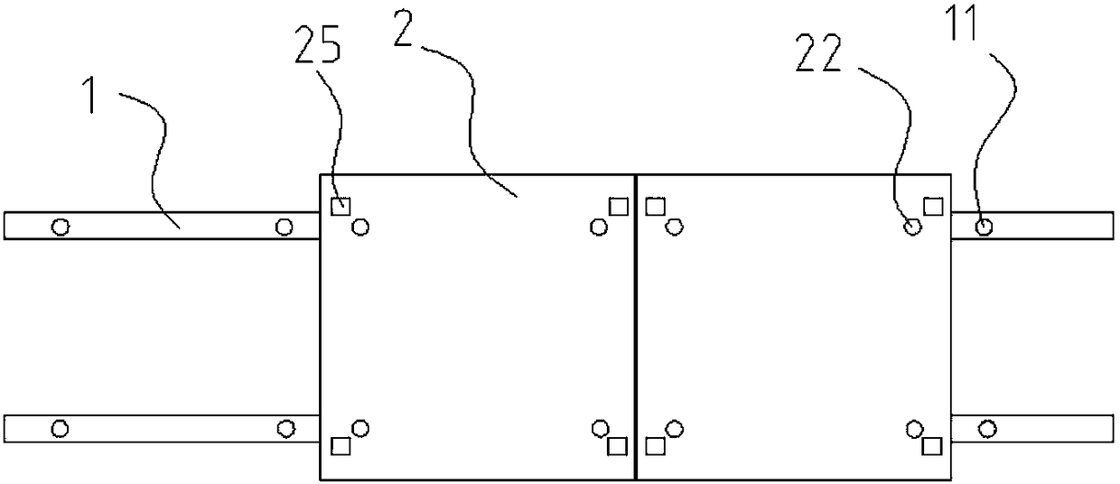
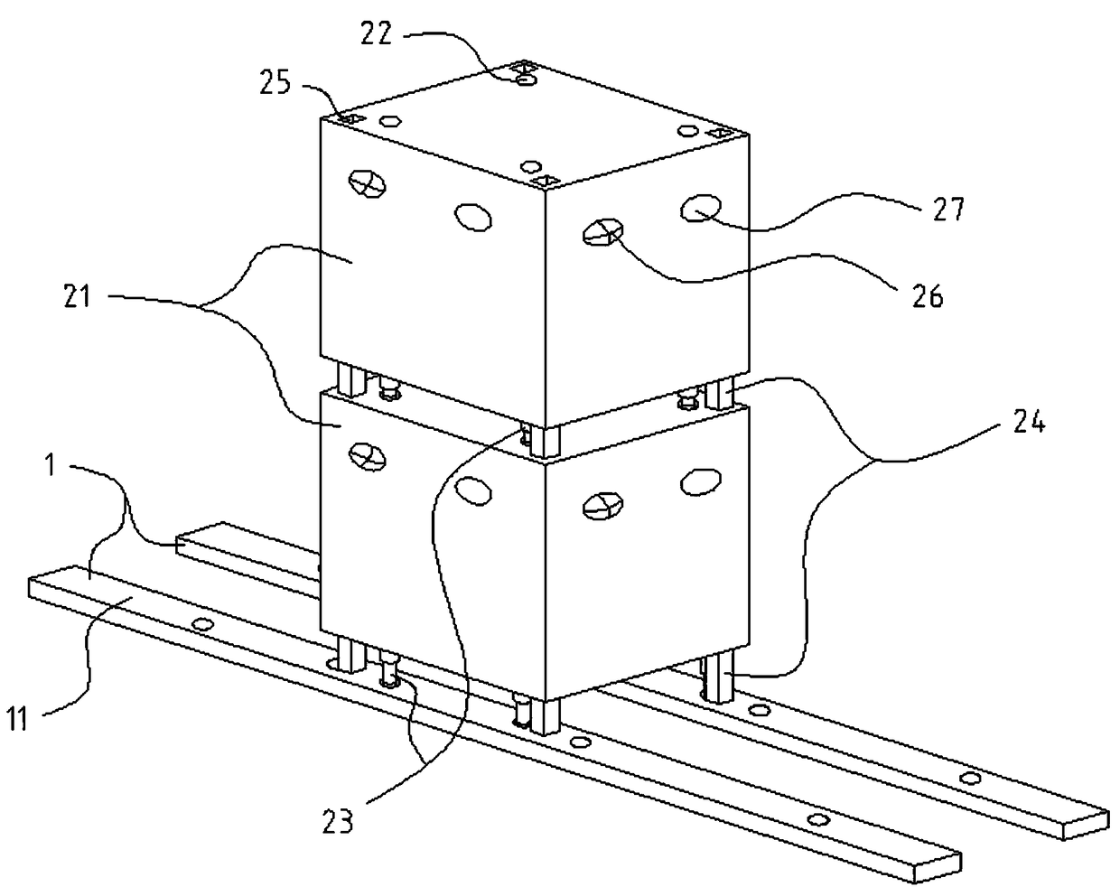
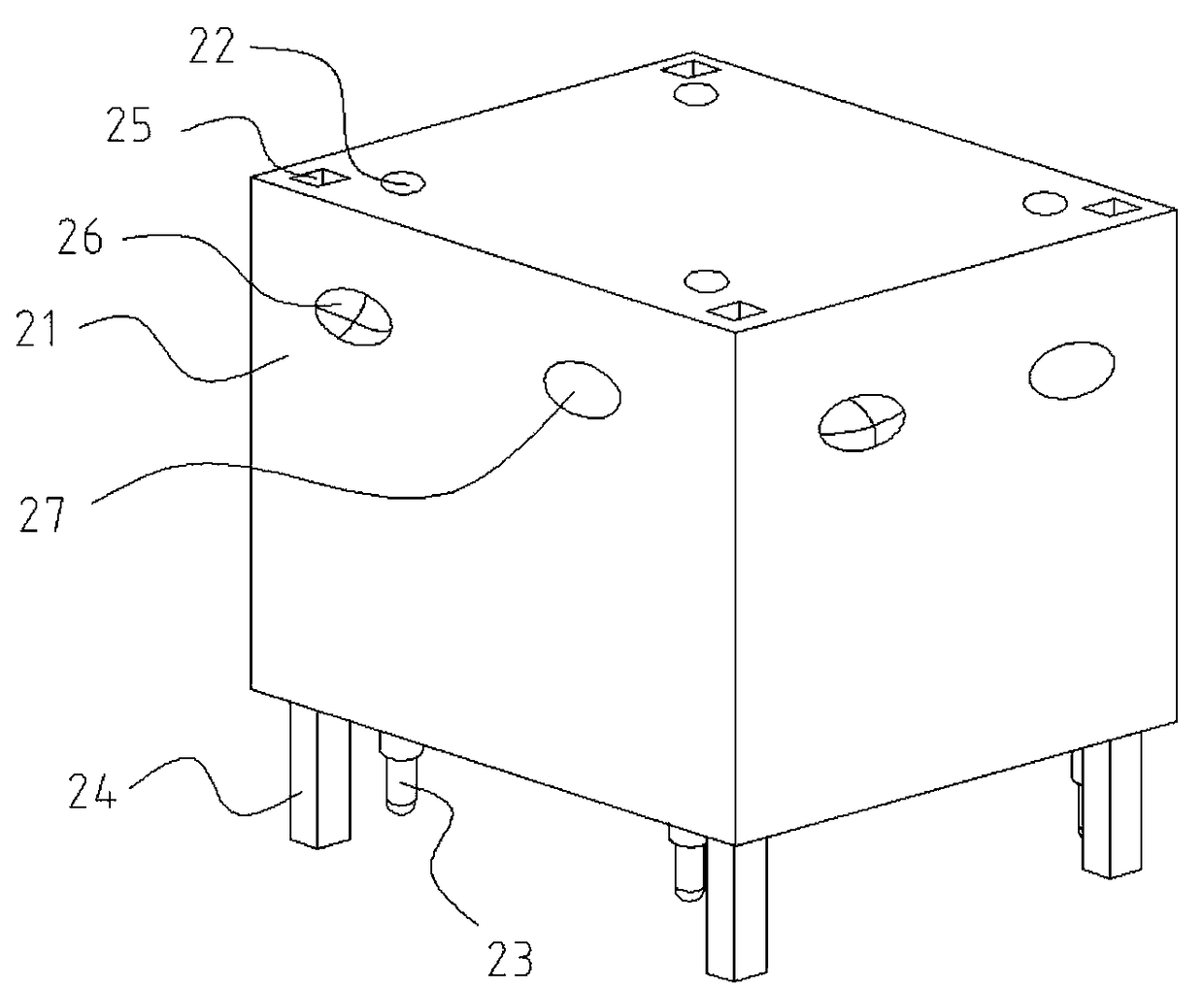
[0024] figure 1 It is a structural diagram of an embodiment of a refrigeration device and its placement method of the present invention; figure 2 It is a structural diagram of a viewing angle of a preferred embodiment of the present invention; image 3 It is a structural diagram of a refrigeration equipment in a preferred embodiment of the present invention; Figure 4 It is a structural diagram of a guide rail in a preferred embodiment of the present invention. Such as figure 1 , figure 2 , image 3 as well as Figure 4 As shown, the refrigeration equipment provided by this embodimen...


PUM


Abstract

The invention provides a refrigeration plant and its placing method, and belongs to the technical field of the refrigeration plant. A refrigeration plant comprises a power supply track paved in a stacking zone; the power supply track comprises two electrified lead rails spaced in parallel; lead rail contact points or tray cars are arranged on the lead rails; meanwhile, the lead rails are stacked with refrigeration plants of a refrigeration case with a contact foot and a contact point. The contact foot at the bottom part of the refrigeration case is directly contacted with the lead rail contactpoint on the electrified lead rails or with the tray cars with conductive wheels; the contact foot of the refrigeration case at the upper layer is contacted with the case contact point at the top part of the refrigeration case body at the lower layer, thus the power energy transmission between the lead rails and the refrigeration case or between the refrigeration plants is realized, the layout inconvenience and safety hidden trouble caused by arranging leads are avoided; every lead rail is a dismountable structure, and both ends are connected to the other lead rail, the refrigeration plant can adapt to the area of different stacking zones, is convenient to expand; every device is an independent structure, and more convenient to transport.

Description

technical field [0001] The invention relates to the technical field of refrigeration equipment, in particular to a refrigeration equipment and its placement method. Background technique [0002] The low temperature generated by refrigeration equipment can better maintain the state of items and ensure their freshness. Therefore, refrigeration equipment has been widely used in today's society. [0003] Traditional refrigeration equipment includes cold storage and cold boxes. The cold storage has a large space, but the construction cost is high, the energy consumed for maintenance is large, and it is inconvenient to carry and not convenient for later expansion. At the same time, it will cause a large amount of cold air to leak out when entering and leaving the cold storage. , resulting in energy loss; the traditional cold box is small in size and easy to carry, but each cold box is equipped with its own power supply system. The intricate wiring layout is not only difficult to ...

Claims


Application Information

Patent Timeline
Patent Type & Authority Applications(China)
IPC IPC(8): F25D11/00F25D23/00
CPCF25D11/00F25D23/00F25D2400/32
Inventor 程路
Owner CHINA STIRLING ENGINE MFG
Why Eureka
Try Eureka