Circuit board detection method and device
A detection method and detection device technology, applied in the direction of electronic circuit testing, instrumentation, computer control, etc., can solve the problems of high cost and low detection efficiency, and achieve the effects of simple operation, simplified testing process, and strong practicability
- Summary
- Abstract
- Description
- Claims
- Application Information
AI Technical Summary
Problems solved by technology
Method used
Image

Examples
Embodiment 1
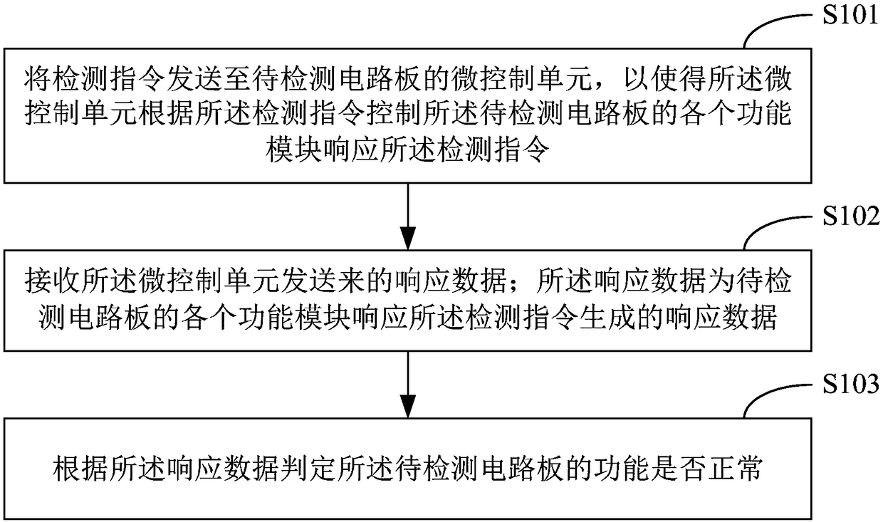
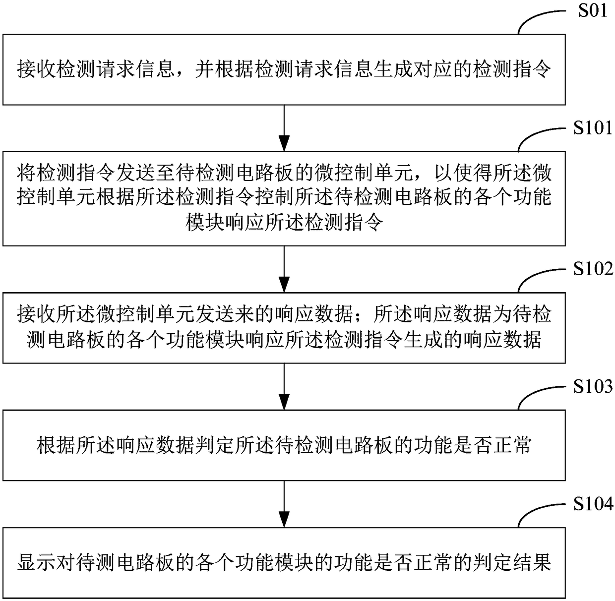
[0024] figure 1 The implementation flow of the circuit board detection method provided by Embodiment 1 of the present invention is shown. In this embodiment, the circuit board detection method is used to detect whether the function of each functional module of the circuit board with the micro control unit is normal. see figure 1 , the implementation process of the circuit board detection method is described in detail as follows:
[0025] Step S101 , sending a detection instruction to the micro-control unit of the circuit board to be detected, so that the micro-control unit controls each functional module of the circuit board to be detected to respond to the detection instruction according to the detection instruction.
[0026] In this embodiment, different types or models of circuit boards to be tested (PCBA, Printed Circuit Board Assembly) correspond to different detection instructions. The user can set a corresponding detection instruction according to the type or model o...
Embodiment 2
[0057] Corresponding to the circuit board detection method described in the above embodiment, Figure 4 A structural diagram of the circuit board detection device provided by the embodiment of the present invention is shown. For ease of description, only the parts related to this embodiment are shown.
[0058] refer to Figure 4 , the device is used to detect whether the function of each functional module of the circuit board with the micro control unit is normal, and the circuit board detection device may include a command sending module 401 , a receiving module 402 and a judging module 403 . in:
[0059] The instruction sending module 401 is configured to send a detection instruction to the micro-control unit of the circuit board to be detected, so that the micro-control unit controls each functional module of the circuit board to be detected to respond to the detection instruction according to the detection instruction.
[0060] The receiving module 402 is configured to ...
Embodiment 3
[0072] see Figure 6 , is a schematic block diagram of a circuit board detection device provided in Embodiment 3 of the present invention. The circuit board detection device as shown in the figure may include: one or more processors 601 (only one is shown in the figure); one or more input devices 602 (only one is shown in the figure), and one or more output devices 603 (only one is shown in the figure) and memory 604. The aforementioned processor 601 , input device 602 , output device 603 and memory 604 are connected through a bus 605 . The memory 604 is used to store instructions, and the processor 601 is used to execute the instructions stored in the memory 604 . in:
[0073] The processor 601 is configured to send a detection instruction to the micro-control unit of the circuit board to be detected through the output device 603, so that the micro-control unit controls each function of the circuit board to be detected according to the detection instruction The module res...
PUM
 Abstract
Description
Claims
Application Information
 - R&D
- Intellectual Property
- Life Sciences
- Materials
- Tech Scout
- Unparalleled Data Quality
- Higher Quality Content
- 60% Fewer Hallucinations
Browse by: Latest US Patents, China's latest patents, Technical Efficacy Thesaurus, Application Domain, Technology Topic, Popular Technical Reports.
© 2025 PatSnap. All rights reserved.Legal|Privacy policy|Modern Slavery Act Transparency Statement|Sitemap|About US| Contact US: help@patsnap.com