Motor detection device for automobile manufacturing

A detection device and automobile manufacturing technology, which is applied in the direction of measuring devices, measuring device casings, motor generator testing, etc., can solve the problems of inaccuracy, lack of unified standards, low efficiency of manual detection, etc., and achieve rigorous design, convenient and fast use, The effect of simple structure

Active Publication Date: 2018-06-29
QINGDAO AIPU INTELLIGENT INSTR
View PDF14 Cites 4 Cited by
  • Summary
  • Abstract
  • Description
  • Claims
  • Application Information

AI Technical Summary

Problems solved by technology

[0006] In order to overcome the shortcomings of low manual detection efficiency, inaccuracy, and lack of unified standards, the technical problem to be solved by the present invention is to provide a motor detection method for automobile manufacturing that can replace manual motor detection, has unified detection standards, and is convenient and quick to use. device

Method used


Image

  • Motor detection device for automobile manufacturing
  • Motor detection device for automobile manufacturing
  • Motor detection device for automobile manufacturing

Examples


Embodiment 1

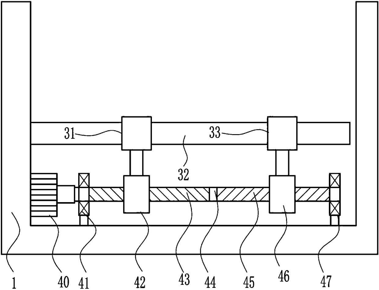
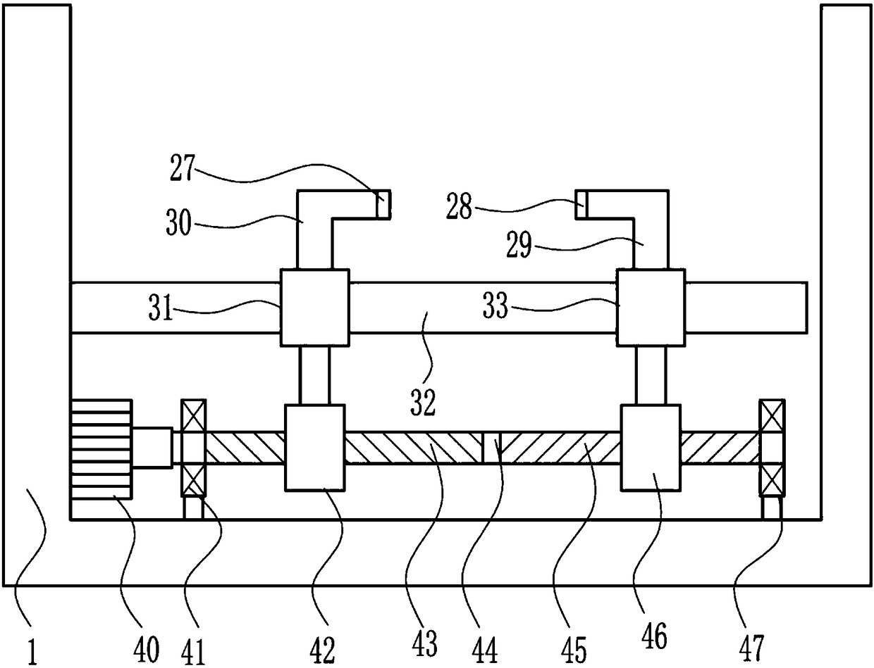
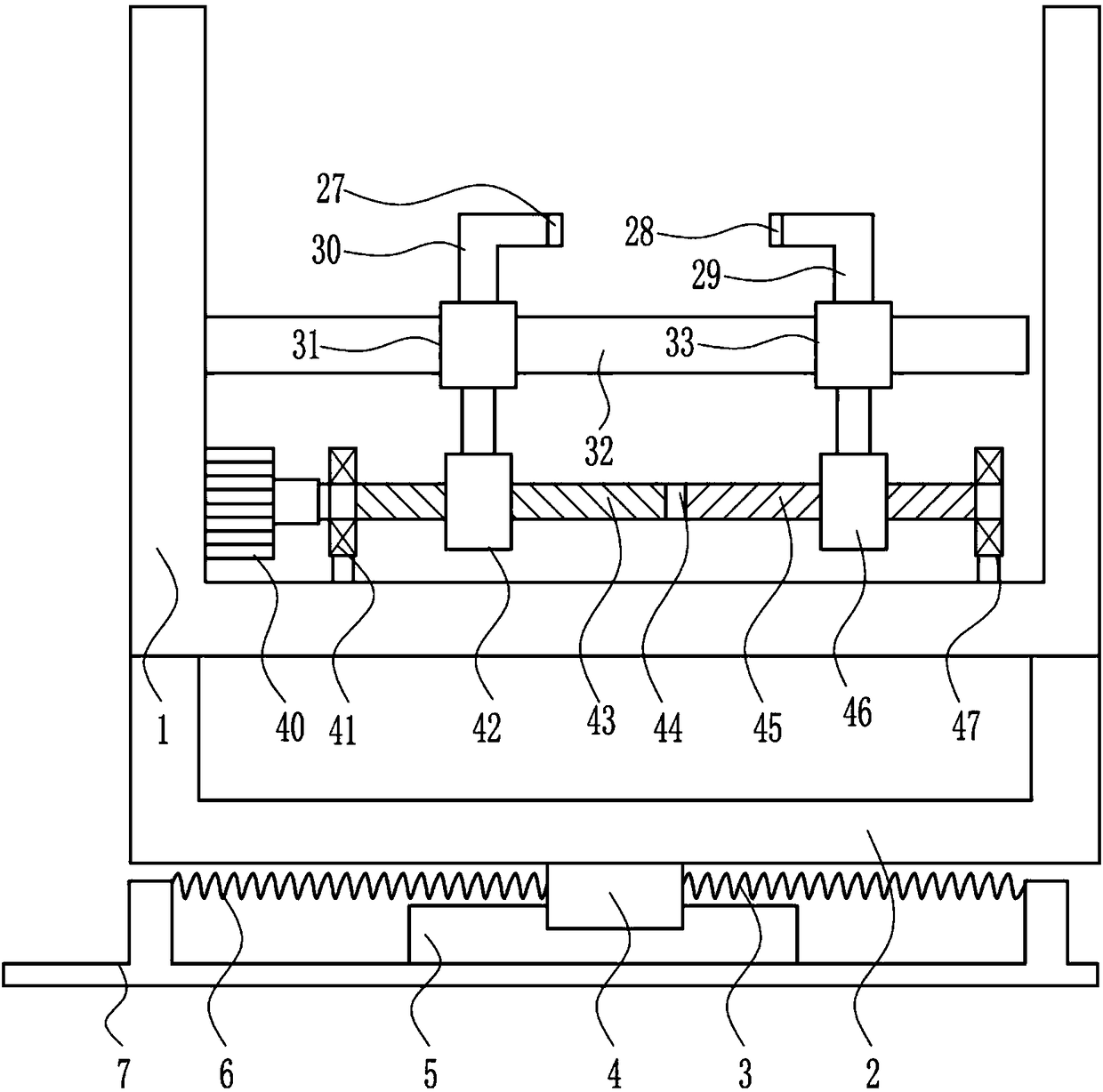
[0025] A motor detection device for automobile manufacturing, such as Figure 1-4 As shown, it includes a fixed frame 1, a first sliding sleeve 31, a sliding rod 32, a second sliding sleeve 33, a second motor 40, a second bearing 41, a first screw nut 42, a first screw rod 43, and a connecting shaft 44 , the second screw mandrel 45, the second screw nut 46 and the seventh bearing 47, the second motor 40 is installed on the right side of the left wall of the fixed frame 1, the first screw mandrel 43 is installed on the output shaft of the second motor 40, the first wire The connecting shaft 44 is installed on the right end of the rod 43, the second screw mandrel 45 is installed on the right end of the connecting shaft 44, the second bearing 41 is installed on the left part of the fixed frame 1, the seventh bearing 47 is installed on the right part of the fixed frame 1, and the second bearing 41 Link to each other with the first screw mandrel 43 through the mode of interference ...

Embodiment 2

[0027] A motor detection device for automobile manufacturing, such as Figure 1-4 As shown, it includes a fixed frame 1, a first sliding sleeve 31, a sliding rod 32, a second sliding sleeve 33, a second motor 40, a second bearing 41, a first screw nut 42, a first screw rod 43, and a connecting shaft 44 , the second screw mandrel 45, the second screw nut 46 and the seventh bearing 47, the second motor 40 is installed on the right side of the left wall of the fixed frame 1, the first screw mandrel 43 is installed on the output shaft of the second motor 40, the first wire The connecting shaft 44 is installed on the right end of the rod 43, the second screw mandrel 45 is installed on the right end of the connecting shaft 44, the second bearing 41 is installed on the left part of the fixed frame 1, the seventh bearing 47 is installed on the right part of the fixed frame 1, and the second bearing 41 Link to each other with the first screw mandrel 43 through the mode of interference ...

Embodiment 3

[0030] A motor detection device for automobile manufacturing, such as Figure 1-4 As shown, it includes a fixed frame 1, a first sliding sleeve 31, a sliding rod 32, a second sliding sleeve 33, a second motor 40, a second bearing 41, a first screw nut 42, a first screw rod 43, and a connecting shaft 44 , the second screw mandrel 45, the second screw nut 46 and the seventh bearing 47, the second motor 40 is installed on the right side of the left wall of the fixed frame 1, the first screw mandrel 43 is installed on the output shaft of the second motor 40, the first wire The connecting shaft 44 is installed on the right end of the rod 43, the second screw mandrel 45 is installed on the right end of the connecting shaft 44, the second bearing 41 is installed on the left part of the fixed frame 1, the seventh bearing 47 is installed on the right part of the fixed frame 1, and the second bearing 41 Link to each other with the first screw mandrel 43 through the mode of interference ...


PUM


Abstract

The invention relates to a detection device, particularly to a motor detection device for automobile manufacturing. The invention aims to solve a technical problem of providing a motor detection device for automobile manufacturing, which is capable of replacing manual operation to detect a motor, and is consistent in detection standard, and convenient and quick to use. In order to solve the technical problem, the invention provides the motor detection device for automobile manufacturing, which comprises a fixing frame, a first sliding sleeve, a sliding rod, a second sliding sleeve, a second motor, a second bearing and the like, wherein the second motor is mounted on the right side of the left wall of the fixing frame; a first lead screw is mounted on an output shaft of the second motor; aconnecting shaft is mounted at the right end of the first lead screw. The device is capable of replacing manual operation to detect a motor, and is consistent in detection standard, and convenient andquick to use; with the adoption of the device, whether the motor is qualified can be detected within a short time; the device is convenient to use and simple to operate, extremely facilitates the work of detection workers, is rigorous in design and simple in structure, and meets the accuracy requirement of a factory.

Description

technical field [0001] The invention relates to a detection device, in particular to a motor detection device for automobile manufacturing. Background technique [0002] my country's latest national standard "Terms and Definitions of Vehicles and Trailer Types" has the following definitions for vehicles: non-track-bearing vehicles driven by power and with 4 or more wheels, mainly used for: carrying people and (or) Goods; vehicles towing people and / or goods; special purpose. [0003] A motor is an electromagnetic device that converts or transmits electrical energy according to the law of electromagnetic induction. [0004] With the improvement of people's living standards, there are higher requirements for travel, and people's needs for cars are getting higher and higher. At present, motors need to be tested before assembly of cars to ensure safety. Manual testing is inefficient and not enough Accurate, there is no uniform standard. Therefore, it is urgent to develop a motor...

Claims


Application Information

Patent Timeline
Patent Type & Authority Applications(China)
IPC IPC(8): G01R31/34G01R1/04
CPCG01R1/0425G01R31/34
Inventor 施佳云郑远茹王建华
Owner QINGDAO AIPU INTELLIGENT INSTR
Why Eureka
Try Eureka