Cam curve design method for cap screwing machine based on polynomial fitting

A polynomial fitting, cam curve technology, applied in the field of mechanical design, can solve the problems of large noise of capping machine, high polynomial power, large dynamic stress of components, etc., to achieve improved dynamic performance, good smoothness, and noise reduction and vibration effects

Inactive Publication Date: 2018-06-29
JIANGNAN UNIV
View PDF7 Cites 4 Cited by
  • Summary
  • Abstract
  • Description
  • Claims
  • Application Information

AI Technical Summary

Problems solved by technology

This method will directly lead to the cam curve only satisfying the continuous speed. When the cam is running at high speed, due to the flexible impact, the dynamic stress of the components is relatively large. When the capping machine is working on site, it is noisy, easy to wear, and the operating efficiency is very low.
[0004] The polynomial design method can effectively i

Method used


Image

  • Cam curve design method for cap screwing machine based on polynomial fitting
  • Cam curve design method for cap screwing machine based on polynomial fitting
  • Cam curve design method for cap screwing machine based on polynomial fitting

Examples


Embodiment 1

[0031] The present invention proposes a method for designing a cam curve of a capping machine based on polynomial fitting, comprising the following steps:

[0032] Step 1. Take the data that the cam follower of the capping machine reaches the corresponding displacement point at the corresponding angle as the key points; these key points generally support the capping machine to complete functions such as capping, bottle feeding, and capping;

[0033] Step 2. Dimensionalize the key point data to obtain dimensionless time T and dimensionless displacement S;

[0034] Step 3, write the polynomial fitting program by MATLAB, combine the constraint condition to key point displacement, utilize least squares method, obtain n degree polynomial fitting cam curve displacement function expression and graph, described n degree polynomial fitting cam curve displacement The function expression is: S=C 0 +C 1 T+...+C n T n , where n is 5, 6 or 7, C 0 , C 1 ,...,C n is a coefficient; in o...

Embodiment 2

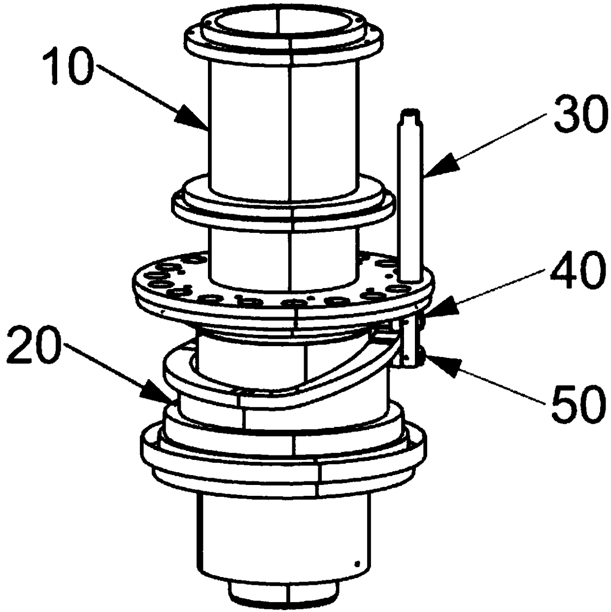
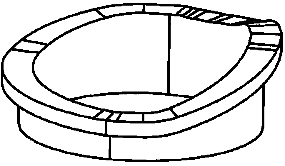
[0056] Such as figure 1 As shown, the capping machine cam mechanism used in the present invention is mainly composed of cam central shaft 10, cam 20, follower 30, follower upper roller 40 and follower lower roller 50 and other components. During operation, the cam portion remains fixed, the cam central shaft 10 rotates 20 relative to the cam, and the upper roller 40 and the lower roller 50 of the follower roll around the cam central shaft 10 along the cam profile, pushing the cam follower 30 to move up and down along the hub.

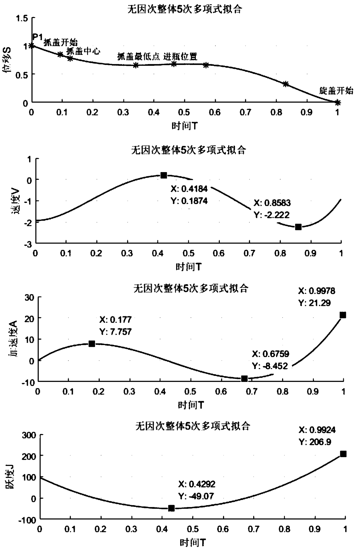
[0057] Such as figure 2 As shown, the cam follower of the capping machine used needs to reach the corresponding displacement point at the corresponding angle to complete the actions from bottle output, cap grasping, bottle feeding to cap screwing. These displacement points are referred to as key points, and the allowable design error at the key points is specified to be 1mm. It is known that the cam mechanism exits the bottle position point (0°) to P1...


PUM


Abstract

The invention proposes a cam curve design method for a cap screwing machine based on polynomial fitting. Firstly, various key points determined by the cap screwing machine for completing a cap screwing function are obtained; secondly, in order to avoid the influence of dimensions, the expression mode of each key point is transformed into the relationship between time and displacement, and then thetime and displacement are made to be dimensionless; furthermore, local control points are appropriately added on the basis of shapes and errors of control curves, 5 times, 6 times, 7 times polynomialfitting methods are respectively used for fitting the points, and cam curve expression and cam curve maps are output; finally, the kinematics and dynamics performance of the three polynomial fittingcam curves are compared and analyzed to obtain an optimal curve, and the processing of the cap screwing machine is performed on the optimal curve.

Description

technical field [0001] The invention belongs to the field of mechanical design, in particular to a method for designing a cam curve of a capping machine based on polynomial fitting. Background technique [0002] Since the cam mechanism can almost complete all kinds of variable speed movements, and can adjust the speed according to the needs, with high precision and low cost, there are still many occasions where the cam mechanism is applied in modern machinery. Nowadays, there are many ways to improve the accuracy of the cam mechanism, and the research and design of the cam curve is the most important and the most effective. The traditional research method of cam curves is to combine some commonly used motion curves to meet the actual motion requirements of cams, and many commonly used standard cam curves have been formed, but the combined motion curves are not continuous at the high-order derivatives. The operating speed of the cam mechanism is constantly increasing, and th...

Claims


Application Information

Patent Timeline
IPC IPC(8): G06F17/50
CPCG06F30/17G06F30/20
Inventor 吴佳何雪明刘平
Owner JIANGNAN UNIV
Why Eureka
Try Eureka