Uniform projection type electron optical structure

An electron optics and projection technology, applied in electron multiplier tubes, electron multiplier details, circuits, etc., can solve the problems that affect the uniformity of projection, the surface of the grid is not easy to process, and the size of the electron beam is not easy to adjust, etc., to achieve uniformity Good performance and easy adjustment

Active Publication Date: 2018-06-29
上海极优威光电科技有限公司
View PDF4 Cites 0 Cited by
  • Summary
  • Abstract
  • Description
  • Claims
  • Application Information

AI Technical Summary

Problems solved by technology

[0005] (3) The high-quality grid surface is not easy to process, which affects the projection uniformity;
[0006] (4) The grid aperture affects the projection uniformity, and the projection area is actually a virtual image of the grid aperture, resulting in a large number of point-like strong beam areas;
[0007] (5) The size of the projection area is not easy to adjust, and the size of the electron beam current is not easy to adjust

Method used


Image

  • Uniform projection type electron optical structure
  • Uniform projection type electron optical structure

Examples


Embodiment Construction

[0025] In order to enable those skilled in the art to better understand the technical solutions in the present application, the technical solutions in the embodiments of the present application will be clearly and completely described below in conjunction with the drawings in the embodiments of the present application. Obviously, the described The embodiments are only some of the embodiments of the present application, but not all of them. Based on the embodiments in this application, all other embodiments obtained by persons of ordinary skill in the art without creative efforts shall fall within the scope of protection of this application.

[0026] The specific implementation manners of the embodiments of the present application will be further described in detail below in conjunction with the accompanying drawings.

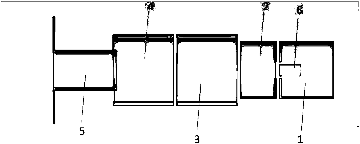
[0027] figure 1 Shown is a schematic diagram of the uniform projection electron optical structure of the embodiment of the present application, where 6 represe...


PUM


Abstract

The invention discloses a uniform projection type electron optical structure, which comprises a cathode region, a beam-forming region, and an electron gun outlet region; a cathode is arranged in the cathode region, the cathode projects electrons, and a cathode emission surface is formed; from the cathode emission surface, the electrons pass through the beam-forming region and the electron gun outlet region to emit, ultimately forming a projection region; the beam-forming region comprises at least two subbeam-forming regions, each subbeam-forming region is of a metal barrel structure, and moreover, the potentials of all the metal barrels can be separately regulated to control the forms of electron beams in the regions; the beam-forming region generates a primary upside-down real image for the cathode emission surface; the projection region is a secondary upside-down real image of the cathode emission surface, and ultimately, the electrons are uniformly projected. Compared with the priorart, a metal grid does not need to be arranged, a high-voltage electric field is used for being focused to project the secondary upside-down real image of the cathode to a required region, and the uniformity of the electron beam of the projection region is ensured by the optimized structure.

Description

technical field [0001] The invention relates to an electron optical structure, in particular to a uniform projection electron optical structure. Background technique [0002] The traditional projected electron optical structure often focuses the electron beam, but in the application fields of electron beam irradiation modification, irradiation aging and excitation illumination, the electron beam uniformly projected to a certain area is required. There is a uniform projection electron optical structure in the prior art, but it is generally necessary to use a metal grid to shield the focusing effect of the high-voltage electric field. The disadvantages of this structure are as follows: [0003] (1) The grid will intercept electrons and waste part of the electron beam; [0004] (2) The electrons intercepted by the grid generate heat, which causes the grid to deform; [0005] (3) The high-quality grid surface is not easy to process, which affects the projection uniformity; ...

Claims


Application Information

Patent Timeline
Patent Type & Authority Applications(China)
IPC IPC(8): H01J43/28H01J43/06
CPCH01J43/06H01J43/28
Inventor 赵健夏忠平朱滨
Owner 上海极优威光电科技有限公司
Why Eureka
Try Eureka