
Ground-penetrating radar pavement vertical crack detection method based on directional ultra-broadband magnetic dipole antenna

A detection method, the technology of ground penetrating radar, applied in the directions of antenna grounding device, electromagnetic wave detection, antenna grounding switch structure connection, etc., can solve the problems of road surface damage, unfavorable road surface maintenance, difficulty in obtaining abnormal signals of vertical cracks, etc., and achieve resolution high rate effect

Inactive Publication Date: 2020-09-22
JILIN UNIV
View PDF5 Cites 0 Cited by
  • Summary
  • Abstract
  • Description
  • Claims
  • Application Information

AI Technical Summary

Problems solved by technology

[0005] The present invention solves the problems that existing detection methods cause damage to the road surface, which is not conducive to road surface maintenance, and that it is difficult to obtain effective abnormal signals generated by vertical cracks because the electric dipole antenna limits the radiation direction and the magnitude of the passing current, etc., and provides A directional ultra-broadband magnetic dipole antenna and its detection method

Method used


Image

  • Ground-penetrating radar pavement vertical crack detection method based on directional ultra-broadband magnetic dipole antenna
  • Ground-penetrating radar pavement vertical crack detection method based on directional ultra-broadband magnetic dipole antenna
  • Ground-penetrating radar pavement vertical crack detection method based on directional ultra-broadband magnetic dipole antenna

Examples


specific Embodiment approach 1

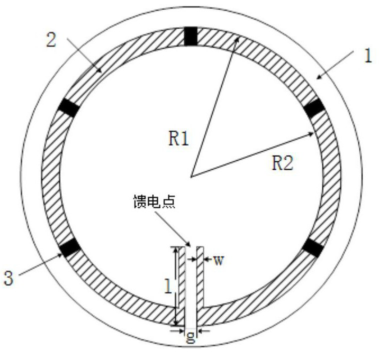
[0016] Specific implementation mode 1. Combination Figure 1 to Figure 5 To illustrate this embodiment, it is based on a directional ultra-broadband magnetic dipole antenna. The circular antenna is composed of an epoxy glass cloth layered copper-clad laminate 1, and the front of the pressure plate 1 is covered with a circular metal copper paste with resistance. sheet 2, the resistors 3 are evenly distributed on the metal copper patch 2, and the feeding point is located directly below the center of the circular metal copper patch 2.

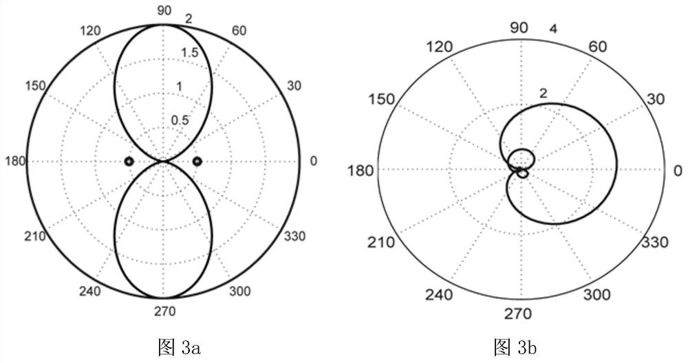
[0017] In this embodiment, in order to realize the ultra-wideband antenna pulse signal, the conventional electric dipole is an electric small antenna with two vibrators, which cannot allow large current to flow. The structure of the magnetic dipole antenna in this embodiment is suitable for large current Passed, it has good differential characteristics, that is, broadband radiation characteristics, the antenna design schematic diagram and specific...

specific Embodiment approach 2

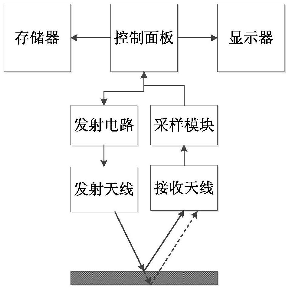
[0018] Specific embodiment two, combine 1 to Figure 5 This embodiment is described. This embodiment is a method for detecting vertical cracks on the pavement using the directional ultra-broadband magnetic dipole antenna described in the first embodiment. The specific process of the method is as follows:

[0019] Step 1. Based on the electrical difference between the target object and the surrounding medium, the transmitting antenna transmits high-frequency short-pulse electromagnetic waves underground. During the propagation, the electromagnetic waves meet the stratum interface and are reflected and transmitted. The receiving antenna obtains the reflected waves and passes sampling The module converts the echo electrical signal, and the host computer records the echo electrical signal and performs preprocessing. The preprocessing includes zero-time correction of the echo electrical signal, DC component elimination, direct wave removal, denoising filtering and gain adjustment pr...


PUM


Abstract

The invention discloses a directional ultra-wideband magnetic dipole antenna and a ground penetrating radar pavement vertical crack detection method, relates to the road and project quality detectiontechnology, and solves the problems of existing detection method that the pavement is damaged and thus hinders pavement maintenance, an effective abnormal signal about vertical crack generation is hard to acquire since an electric dipole antenna limits the radiation direction and the through current, etc. The magnetic dipole antenna is a loop antenna which is formed by an epoxy glass cloth layer copper-clad laminate; the front of the laminate is covered with a circular metal copper patch with resistors; the resistors are uniformly distributed on the metal copper patch; and a feed point is located right below the circle center of the circular metal copper patch. According to the invention, a relatively wide radiation range is realized on the crack development side, and the reflected signalis strong; and moreover, the ultra-wideband magnetic dipole antenna has relatively great frequency bandwidth as well as higher detection resolution on a tiny crack.

Description

technical field [0001] The technology of the invention relates to the detection technology of road and engineering quality, and is mainly aimed at the detection of the width and extension of large inclination or approximate vertical cracks based on ground penetrating radar. Background technique [0002] It is inevitable that disasters will occur during the use of highways. Road diseases, such as broken base, cracked surface, and subsidence of cushion, are mostly caused by cracks in the base below the surface. Vertical cracks usually appear three to five years after the road is opened to traffic, and they mostly occur in driving lanes, overtaking lanes, and hard shoulders. The area where vertical cracks occur has obvious vertical deformation, undulating depressions, relatively regular trend, and presents thick and sparse large cracks, some of which can extend intermittently for hundreds of meters. For the vertical cracks hidden in the base layer in the vertical direction or...

Claims


Application Information

Patent Timeline
Patent Type & Authority Patents(China)
IPC IPC(8): H01Q1/38H01Q1/48H01Q1/50G01V3/12
CPCG01V3/12H01Q1/38H01Q1/48H01Q1/50
Inventor 徐晨阳曾昭发李静槐楠张领张建民贾卓
Owner JILIN UNIV
Learn More