
Miniature rectangular high-voltage electrical connector

A technology of high-voltage electricity and connectors, which is applied in the direction of connection and connection device components, circuits, etc., can solve the problems of cracking at the junction of the shell and the potting sleeve, failure to meet the design requirements, and cumbersome assembly procedures, etc., to achieve environmental adaptation Improved performance, reduced occupied space, and reduced installation difficulty

Pending Publication Date: 2018-06-29
中国电子科技集团公司第四十研究所
View PDF0 Cites 2 Cited by
  • Summary
  • Abstract
  • Description
  • Claims
  • Application Information

AI Technical Summary

Problems solved by technology

[0002] The rectangular high-voltage electrical connector is a product developed according to the application requirements of the equipment. It is used for the connection and transmission of high-voltage signals between the transmitter and the traveling wave tube in the system. It can transmit multiple high-voltage signals at the same time. The existing rectangular high-voltage Piezoelectric connectors include sockets and plugs that cooperate with each other, and the sockets and plugs are mated and connected; as the design trend of transmission equipment is developing towards miniaturization and light weight, the existing rectangular high-voltage electrical connectors have part of the structural load of the plug. The assembly process is cumbersome and cannot meet the new design requirements, and after being subjected to temperature shock, the joint between the shell and the potting sleeve is prone to cracking and falling off, resulting in product failure

Method used


Image

  • Miniature rectangular high-voltage electrical connector
  • Miniature rectangular high-voltage electrical connector
  • Miniature rectangular high-voltage electrical connector

Examples


Embodiment Construction

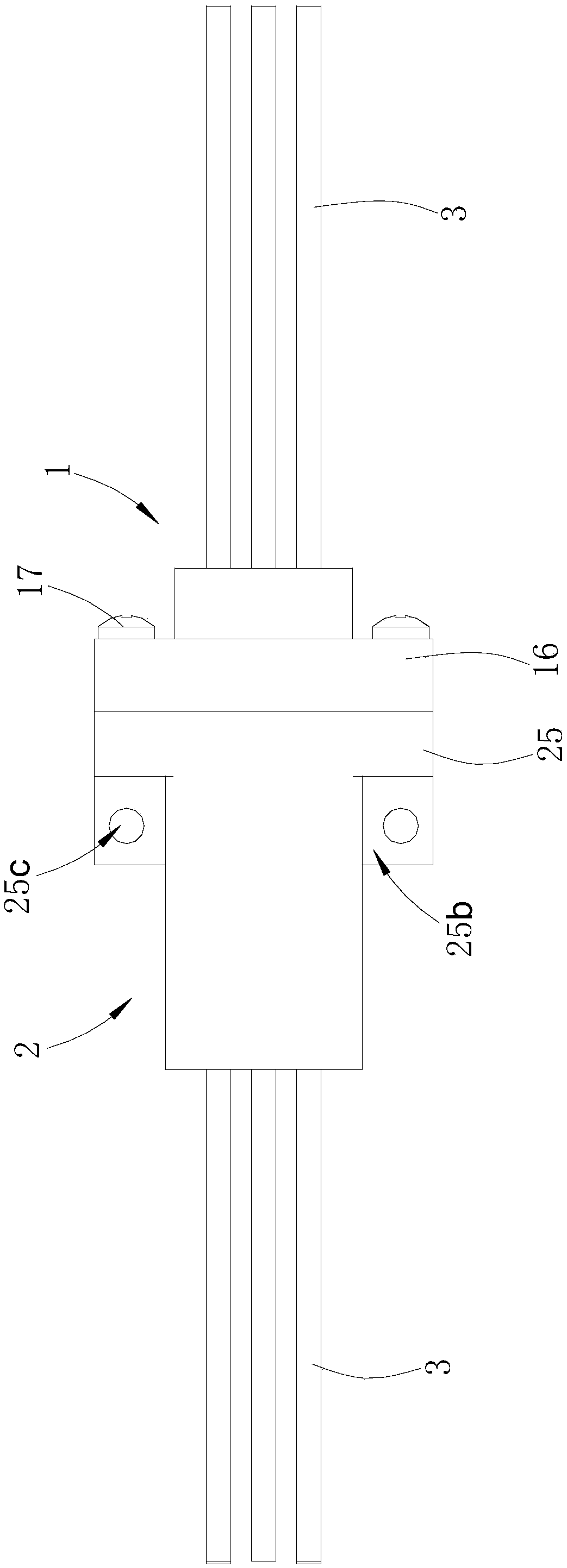
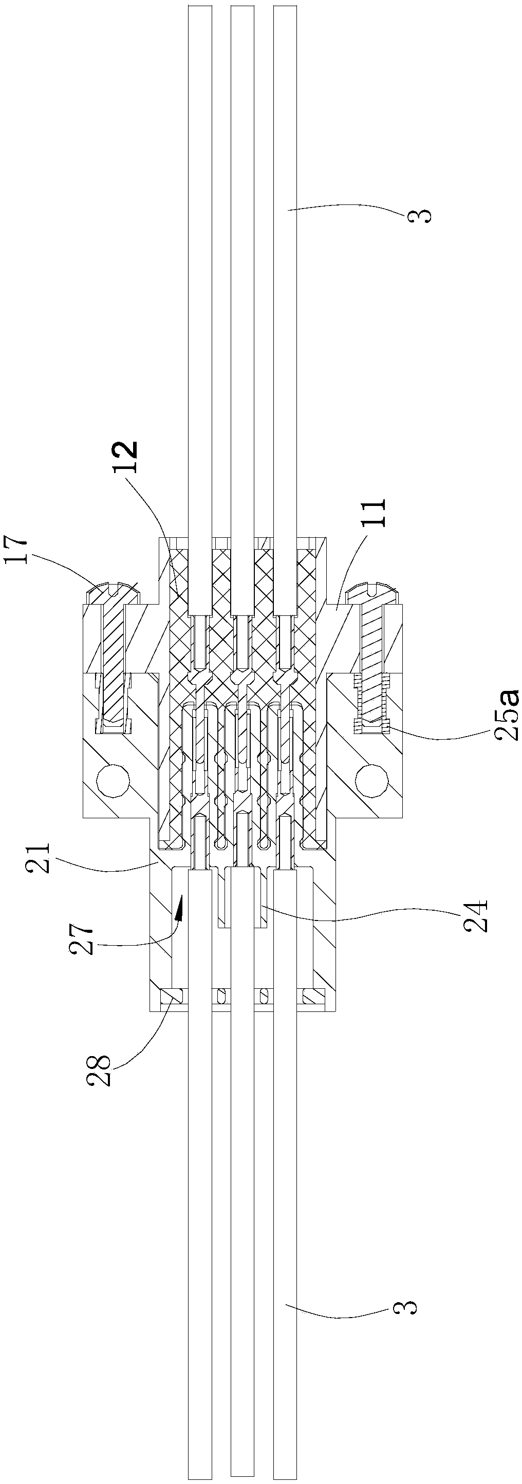
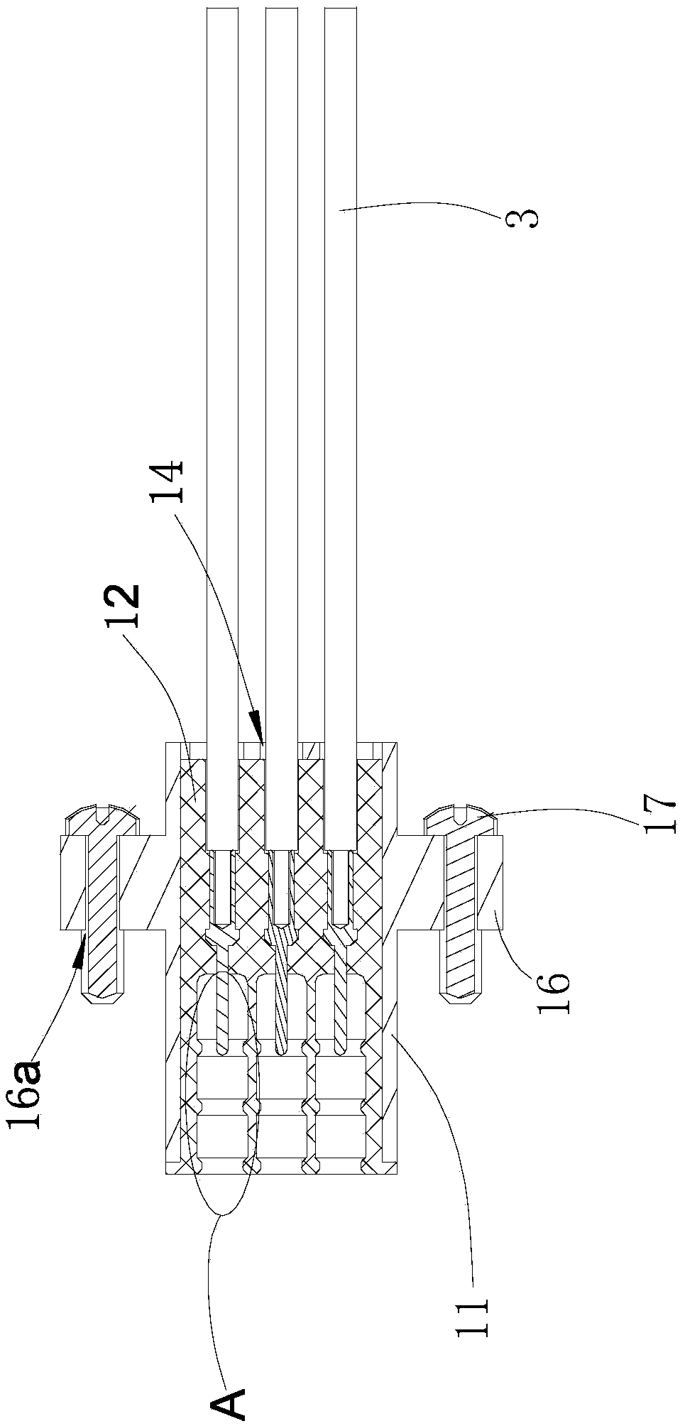
[0025] Such as Figures 1 to 6 as shown,

[0026] The electrical connector includes a socket 1 and a plug 2 adapted to the socket 1 .

[0027] The socket 1 includes a hollow socket housing 11, a soft board 12, and a metal pin 15. The housing 11 is made of insulating material, and the housing 11 is set on the outside of the soft board 12. The material of the soft board 12 is In order to resist low temperature silicone rubber, the installation soft board 12 and the socket housing 11 are sealed and bonded with silicone rubber 3040. The socket housing 11 can reliably hold the insulating installation board. There are six sockets at the rear of the installation soft board 12. The barrel groove 13 and the inserting barrel groove 13 are arranged in two rows in a rectangular shape. There are four sealing convex rings 13a extending inward on the side wall of each inserting barrel groove 13; Groove 14, wire groove 14 and inserting socket groove 13 one-to-one correspondence, is provided...


PUM


Abstract

The invention discloses a miniature rectangular high-voltage electrical connector which comprises a socket and a plug, wherein a socket shell of the socket is arranged on the outer side of a flexiblemounting board in a sleeving manner; a plurality of insertion tube grooves are formed in the rear of the flexible mounting board; a plurality of wire slots are formed in the front of the flexible mounting board; contact pins are arranged between the wire slots and the insertion tube grooves; front ends of the contact pins stretch into the insertion tube grooves; an inner hole of a plug shell of the plug is partitioned into a glue filling groove in the rear side and an insertion groove in the front side by virtue of a middle plate; the front end face of the middle plate extends into the insertion groove to form multiple insertion tubes; through holes communicated with the glue filling groove and the insertion groove are formed in the insertion tubes; metal sleeves are arranged in the through holes of the insertion tubes; jacks are formed in the metal sleeves; a sealing cover plate is arranged on a rear end face of the plug shell; and a plurality of high voltage wires run through the sealing cover plate and stretch into the through holes of the insertion tubes so as to be connected with the metal sleeves. The miniature rectangular high-voltage electrical connector disclosed by the invention has the beneficial effects that the structure is simplified and miniaturized, and the requirement of stably transmitting multi-path high-voltage signals can be met.

Description

technical field [0001] The invention relates to a miniaturized rectangular high-voltage electrical connector. Background technique [0002] The rectangular high-voltage electrical connector is a product developed according to the application requirements of the equipment. It is used for the connection and transmission of high-voltage signals between the transmitter and the traveling wave tube in the system. It can transmit multiple high-voltage signals at the same time. The existing rectangular high-voltage Piezoelectric connectors include sockets and plugs that cooperate with each other, and the sockets and plugs are mated and connected; as the design trend of transmission equipment is developing towards miniaturization and light weight, the existing rectangular high-voltage electrical connectors have part of the structural load of the plug. The assembly process is cumbersome and cannot meet the new design requirements. Moreover, after being subjected to temperature shock, ...

Claims


Application Information

Patent Timeline
Patent Type & Authority Applications(China)
IPC IPC(8): H01R13/533H01R13/53H01R13/504H01R13/405H01R13/11H01R13/621
CPCH01R13/11H01R13/405H01R13/504H01R13/53H01R13/533H01R13/6215
Inventor 程德帅彭长江张洁李岩
Owner 中国电子科技集团公司第四十研究所
Learn More