Improved power cable laying equipment

An improved technology for power cables, applied in cable laying equipment, cable installation, cable installation devices, etc., can solve the problems of complex structure and low efficiency, and achieve the effect of convenient operation and simple structure

Inactive Publication Date: 2018-06-29
广州市灵汐科技有限公司
View PDF0 Cites 0 Cited by
  • Summary
  • Abstract
  • Description
  • Claims
  • Application Information

AI Technical Summary

Problems solved by technology

[0002] In the process of electric power construction, it is usually necessary to lay cables on the ground. Before the cables are laid, a groove that can accommodate the cables needs to be dug on the ground. The structure of the equipment used to dig hook grooves in the prior art is too complicated, and Inefficient use

Method used


Image

  • Improved power cable laying equipment
  • Improved power cable laying equipment
  • Improved power cable laying equipment

Examples


Embodiment Construction

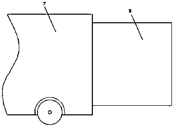
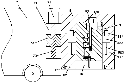
[0016] like figure 1 , figure 2 and image 3 As shown, an improved power cable laying equipment of the present invention includes a push frame 7 and a loading frame 8 that slides up and down and is installed on the push frame 7, and the push frame 7 is provided with an opening to After the assembly groove 71, a sliding seat 72 is installed in the sliding fit of the assembly groove 71, and a screw-shaped column 73 extending up and down is installed in the sliding seat 72, and the bottom extension section of the screw-shaped column 73 is connected to the The bottom end wall of the assembly groove 71 is rotatably connected, the top extension section of the screw-shaped column 73 is connected with the main driving machine 74, and the outer surface of the main driving machine 74 is installed in the inner wall of the upper side of the assembly groove 71 And fixedly fit and connected, the sliding seat 72 is fixedly installed with the loading frame 8, and the bottom end surface of ...


PUM


Abstract

The invention discloses improved power cable laying equipment which comprises a pushing frame and a carrying rack, wherein the carrying rack is mounted on the pushing frame in an up and down sliding manner; an assembling groove which is opened backwards is formed in the pushing frame; a sliding base is mounted in the assembling groove in a sliding matching manner; a spiral column which extends upand down is mounted in the sliding base in a spiral matching manner; a bottom extension section of the spiral column is rotationally connected with the bottom end wall of the assembling groove in match; the top extension section of the spiral column is connected with a main driving machine in match; the outer surface of the main driving machine is mounted on the inner wall of the upper side of theassembling groove and is fixed and connected in match; the sliding base is fixedly mounted with the carrying rack; an accommodation cavity which extends upwards is formed in the bottom end surface ofthe carrying rack. The improved power cable laying equipment is simple in structure and convenient to move, automatic folding and unfolding functions of a sliding rack can be achieved, convenience can be brought to movement, and the working efficiency and the security can be improved.

Description

technical field [0001] The invention relates to the technical field of cable laying, in particular to an improved power cable laying equipment. Background technique [0002] In the process of electric power construction, it is usually necessary to lay the cables on the ground. Before the cables are laid, a groove that can accommodate the cables needs to be excavated on the ground. The structure of the equipment used to excavate the hook grooves in the prior art is too complicated, and Inefficient use. Contents of the invention [0003] The technical problem to be solved by the present invention is to provide an improved power cable laying equipment, which can solve the above-mentioned problems in the prior art. [0004] The present invention is achieved through the following technical solutions: An improved power cable laying equipment of the present invention includes a push frame and a loading frame that slides up and down and is installed on the push frame. An assembl...

Claims


Application Information

Patent Timeline
Patent Type & Authority Applications(China)
IPC IPC(8): H02G1/08
CPCH02G1/085
Inventor 叶翠颖
Owner 广州市灵汐科技有限公司
Why Eureka
Try Eureka