Ejection-out type heat radiating device and electronic calculation equipment

A heat dissipation device and pop-up technology, which is applied in the structural parts of electrical equipment, electrical components, cooling/ventilation/heating transformation, etc., can solve the problems of increased radiator volume, loud noise, and high cost, and achieve increased convection speed, The effect of increasing heat dissipation efficiency and increasing heat dissipation efficiency

Pending Publication Date: 2018-06-29
SICHUAN UNIV
View PDF6 Cites 5 Cited by
  • Summary
  • Abstract
  • Description
  • Claims
  • Application Information

AI Technical Summary

Problems solved by technology

However, these two methods will increase the volume of the radiator and increase the cost, and the noise generated when using a high-power and high-speed fan is also relatively large.
Today's smart devices have gradually developed towards miniaturization, so the above two methods of enhancing heat dissipation performance are often difficult to meet actual needs

Method used


Image

  • Ejection-out type heat radiating device and electronic calculation equipment
  • Ejection-out type heat radiating device and electronic calculation equipment
  • Ejection-out type heat radiating device and electronic calculation equipment

Examples


no. 1 example

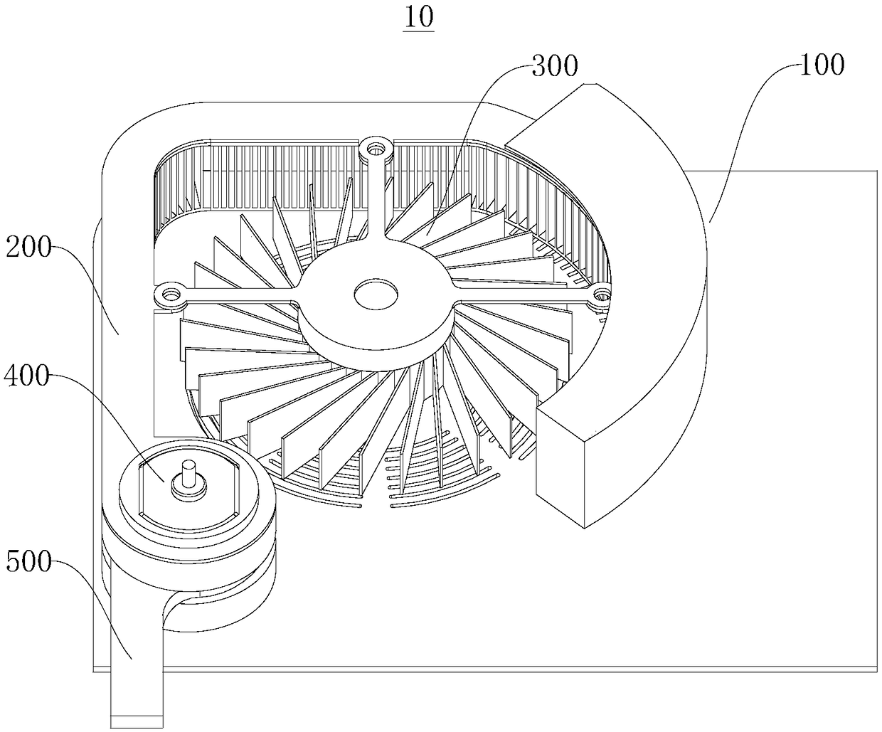
[0042] see figure 1 with figure 2 , this embodiment provides a pop-up heat sink 10, which has the characteristics of simple structure, convenient use, large heat dissipation area and high heat dissipation efficiency, and can adjust the heat dissipation efficiency according to the real-time temperature to further effectively dissipate heat.

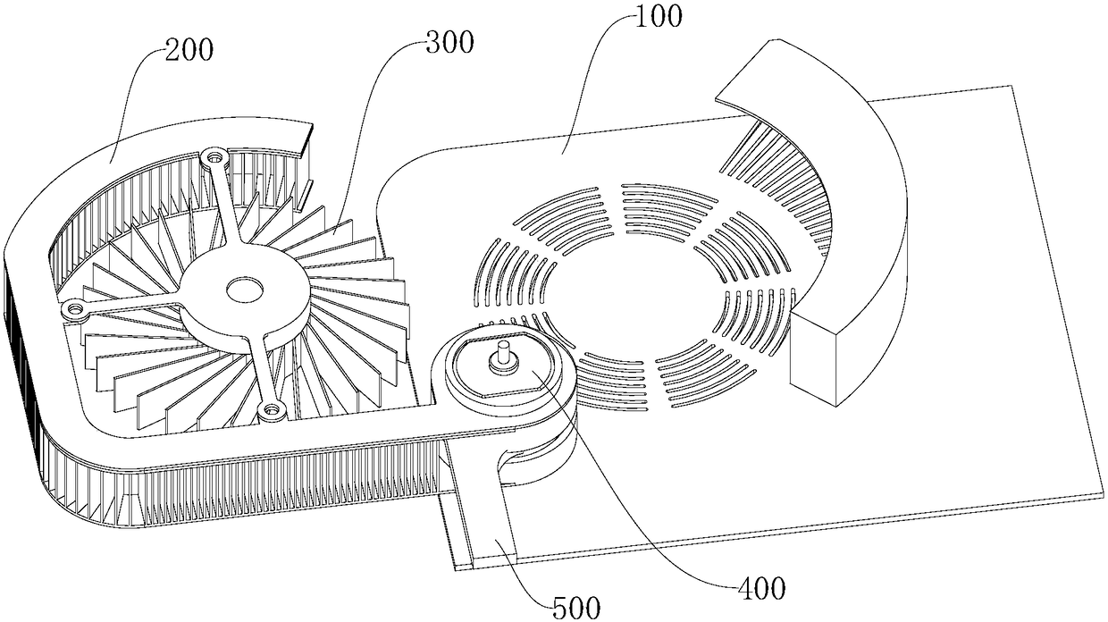
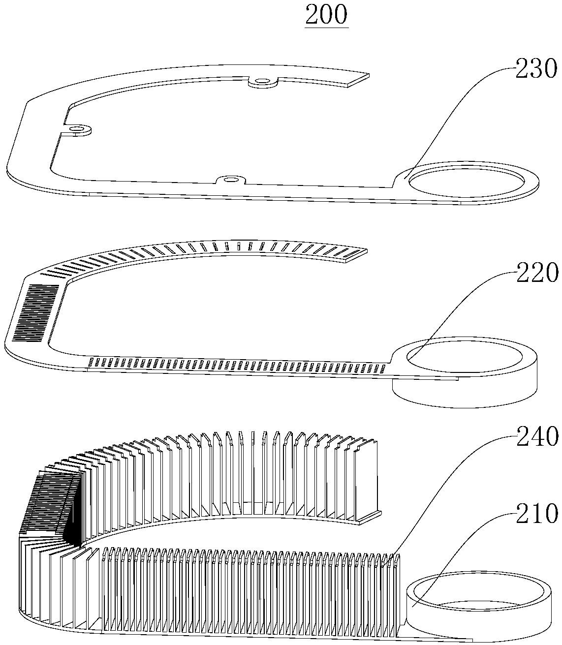
[0043] A pop-up heat dissipation device 10 provided in this embodiment includes a base 100 , a heat dissipation assembly 200 , a fan assembly 300 and a rotation assembly 400 . The rotating assembly 400 is connected with the base 100 . The fan assembly 300 is connected to the cooling assembly 200, and the cooling assembly 200 is connected to the rotating assembly 400, so that the cooling assembly 200 and the fan assembly 300 can rotate from the first position to the second position or from the second position driven by the rotating assembly 400 to the first position.

[0044] It should be noted that, in this embodiment, the first positi...

no. 2 example

[0080] Please refer to Figure 1 to Figure 12 , this embodiment provides an electronic computing device (not shown in the figure), including a housing (not shown in the figure) and the pop-up heat sink 10 as provided in the first embodiment. The pop-up heat sink 10 includes a base 100 , a heat sink assembly 200 , a fan assembly 300 and a rotating assembly 400 . The rotating assembly 400 is connected with the base 100 . The fan assembly 300 is connected to the heat dissipation assembly 200, and the heat dissipation assembly 200 is connected to the rotation assembly 400, so that the heat dissipation assembly 200 and the fan assembly 300 can rotate from the first position to the second position or from the second position driven by the rotation assembly 400 to the first position.

[0081] It should be noted that the electronic computing equipment provided in this embodiment includes, but is not limited to: a server, a personal computer, and the like.


PUM


Abstract

The invention discloses an ejection-out type heat radiating device and electronic calculation equipment, and relates to the technical field of heat radiating. The ejection-out type heat radiating device comprises a base, a heat radiating assembly, a fan assembly and a rotary assembly, wherein the rotary assembly is connected with the base; the fan assembly is connected with the heat radiating assembly; the heat radiating assembly is connected with the rotary assembly, so that the heat radiating assembly and the fan assembly can be driven by the rotary assembly to rotate from a first position to a second position or from the second position to the first position. The invention also provides the electronic calculation equipment containing the ejection-out type heat radiating device. The ejection-out type heat radiating device and the electronic calculation equipment have the characteristics that the structure is simple, the convenience in use is realized, the heat radiating area is large, and the heat radiating efficiency is high; the heat radiating efficiency can be adjusted according to real-time temperature, so as to further effectively radiate heat.

Description

technical field [0001] The invention relates to the technical field of heat dissipation, in particular to a pop-up heat dissipation device and electronic computing equipment. Background technique [0002] This section is intended to provide a background or context for implementations of the invention that are set forth in the claims and detailed description. The descriptions herein are not admitted to be prior art by inclusion in this section. [0003] With the development of electronics and semiconductor technology, electronic components and semiconductor integrated circuits are developing in the direction of high performance, compactness, intelligence and miniaturization, which to a certain extent has also led to the integration and packaging of chips and integrated circuits. Miniaturization and a huge increase in operating frequency. It is well known that high temperatures can seriously affect the performance of integrated circuits. High temperature will not only lead ...

Claims


Application Information

Patent Timeline
Patent Type & Authority Applications(China)
IPC IPC(8): H05K7/20
CPCH05K7/20136H05K7/20172
Inventor 李文强李飞李彦赵玉东杨旭韩怀邦
Owner SICHUAN UNIV
Why Eureka
Try Eureka