Soybean milk making machine

A soymilk maker and machine head technology, which can be used in home appliances, applications, kitchen utensils, etc. It can solve the problems of large noise, high pressure, and easy resonance of food processing machines.

Active Publication Date: 2018-07-03
JOYOUNG CO LTD
View PDF9 Cites 0 Cited by
  • Summary
  • Abstract
  • Description
  • Claims
  • Application Information

AI Technical Summary

Problems solved by technology

[0003] But at the same time, the crushing device also has some adverse effects
Since the pusher is mainly used as an auxiliary pusher, when the pusher pushes the bulk material for centrifugal movement, since the material is not crushed into smaller particles at the beginning, the pressure in the crushing chamber will be high and cannot be discharged in time At this time, the pressure in the crushing chamber will cause the pusher to vibrate at a high frequency, and when the vibration frequency of the motor is equivalent to the vibration frequency of the pusher, the food processor is prone to resonance. When the phenomenon occurs, it will be accompanied by a lot of noise from the whole machine, which will affect people's normal life

Method used


Image

  • Soybean milk making machine
  • Soybean milk making machine
  • Soybean milk making machine

Examples


Embodiment 1

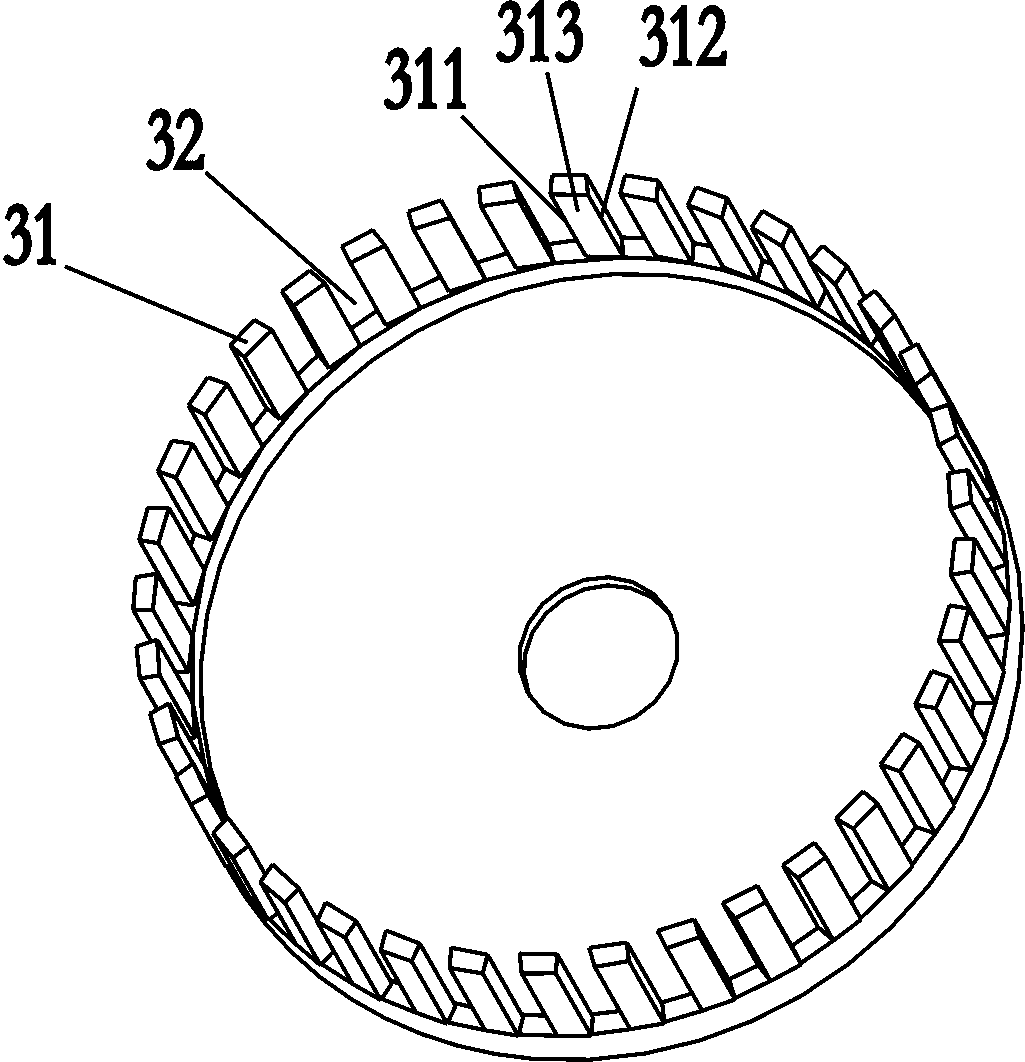
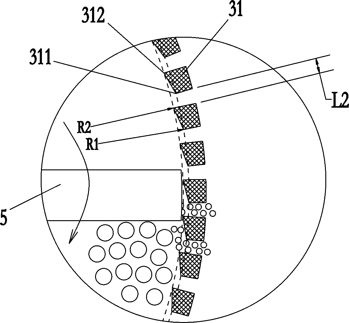
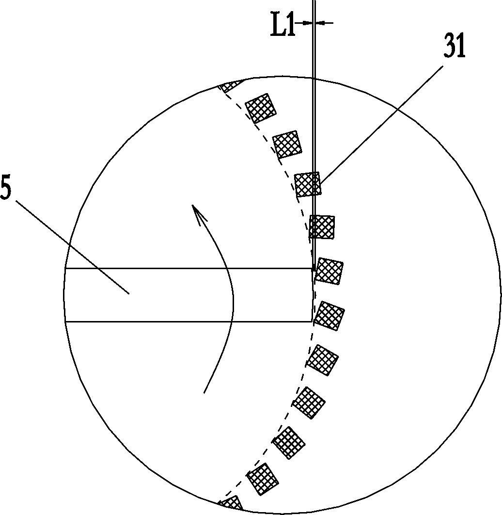
[0033] Such as figure 1 , figure 2 , image 3Shown is a schematic structural diagram of the first embodiment of the present invention. A soybean milk machine, comprising a machine head 1 and a cup body 2, the front end of the machine head is provided with a crushing cover 3, and a motor 4 is arranged in the machine head, and a crushing blade 5 is installed at the end of a rotating shaft 41 driven by the motor 4. The crushing blade 5 is located in the crushing cover 3, the bottom of the crushing cover 3 is open, and the peripheral wall of the crushing cover 3 has a plurality of baffles 31 extending toward the bottom of the cup body 2, and a discharge plate 31 is formed between adjacent baffles 31. The hole 32 is located in the crushing cover. The single baffle 31 has a first edge 311, a second edge 312 and a baffle surface 313 connecting the first edge 311 and the second edge 312. On the same horizontal section, Taking the center of the rotating shaft 41 as the center, the ...

Embodiment 2

[0048] Such as Figure 5 , Figure 6 , Figure 7 Shown is a schematic structural diagram of the second embodiment of the present invention. The difference between this embodiment and Embodiment 1 is that in this embodiment, the pulverizing blade 5 includes multiple blades, and a single blade has a transverse cutting portion 51 and a grinding blade integrated with the cutting portion 51. The grinding part 52 is located at the edge of the cutting part and is bent downward relative to the cutting part 51 , and the grinding part 52 and the spoiler 31 form grinding and pulverization. In addition, a skirt 33 connecting the baffle 31 is provided at the bottom of the baffle 31 , and the bottom of the skirt 33 is flared outwards, which facilitates the slurry at the bottom of the cup to be sucked into the crushing cover.

[0049] In this embodiment, the pulverizing blade has two symmetrical blades, and the blade 511 on the cutting part extends to the grinding part 52, wherein the gri...

Embodiment 3

[0053] Such as Figure 8 , Figure 9 Shown is a schematic structural view of the third embodiment of the present invention. The difference between this embodiment and the second embodiment is that: in this embodiment, the bottom of the crushing cover is also provided with a skirt 33 connected to the spoiler 31, and the inner wall of the skirt 33 is provided with grinding teeth 331 , the grinding portion 52 extends to the skirt 33 and forms grinding and crushing with the grinding teeth 331 .


PUM


Abstract

The invention relates to a kitchen appliance, and in particular to a soybean milk making machine. The soybean milk making machine comprises a a headpiece and a cup body, wherein a crushing cover is arranged at the front end of the headpiece, and an electric motor is arranged in the headpiece; a crushing blade is arranged at the tail end of a rotating shaft driven by the electric motor; the crushing blade is located within the crushing cover; the bottom of the crushing cover is provided with an opening, and a plurality of spoilers, which extend towards the bottom of the cup body, are arranged on the peripheral wall of the crushing cover, and discharge holes are defined between the adjacent spoilers; the soybean milk making machine is characterized in that in the crushing cover, each spoileris provided with a first rib, a second rib and a spoiler plane for connecting the first rib and the second rib; on a same horizontal section, the first rib and the second rib are not located on a same circle that the center of the rotating shaft is taken as the center of the circle; and a distance R1 from the first rib to the center of the circle is greater than a distance R2 from the second ribto the center of the circle. In comparison with kitchen appliances of the prior art, the soybean milk making machine, which is provided with various crushing modes, can be used for making various drinks, and real dregs avoiding without filtering can be achieved, so that soybean milk, when drunk by consumers, is smooth and delicate in taste.

Description

technical field [0001] The invention relates to small kitchen appliances, in particular to a soybean milk maker. Background technique [0002] Prior to this, the inventor applied for an invention patent application with the patent application number CN201511012671.0. This patent application relates to a crushing device for a food processor. The crushing device includes a fixed gear ring, a pusher and a cover. The cover is arranged at one end of the fixed gear ring, and the cover and the fixed gear ring are enclosed to form a crushing chamber. , the pusher is located in the crushing chamber and is driven by the rotating shaft to rotate. The fixed gear has a plurality of fixed teeth arranged in the circumferential direction, and a discharge groove is formed between two adjacent fixed teeth. It is located in the crushing chamber and driven by the rotating shaft. When the pusher rotates, the pusher pushes the mixture of material and water to do centrifugal motion, so that the...

Claims


Application Information

Patent Timeline
Patent Type & Authority Applications(China)
IPC IPC(8): A47J43/044A47J43/07
CPCA47J43/044A47J43/0705A47J43/0711
Inventor 王旭宁尉迟衍敏吴树德周之征徐春辉
Owner JOYOUNG CO LTD
Why Eureka
Try Eureka