

U-shaped tunnel-crossing beam transporting vehicle with adjustable wheel track and beam-feeding method of U-shaped tunnel-crossing beam transporting vehicle
A technology for tunnel beam trucks and beam trucks, which is applied to bridges, bridge construction, erection/assembly of bridges, etc., and can solve problems such as difficult design of supporting low-level tunnel beam trucks, inability to transport beams in tunnels, and large spans , to achieve safe and reliable segmental connection, improve the passability of beam transportation, and reduce the transportation height
- Summary
- Abstract
- Description
- Claims
- Application Information
AI Technical Summary
Problems solved by technology
Method used
Image

Examples
Embodiment Construction
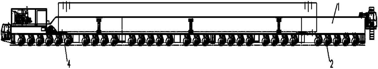
[0042] see Figure 1 to Figure 9, shows the U-shaped tunnel beam transport vehicle with adjustable wheelbase of the present invention.
[0043] See 10A to Figure 10E , shows a schematic diagram of the steps of the beam feeding method of the beam transport vehicle of the present invention.
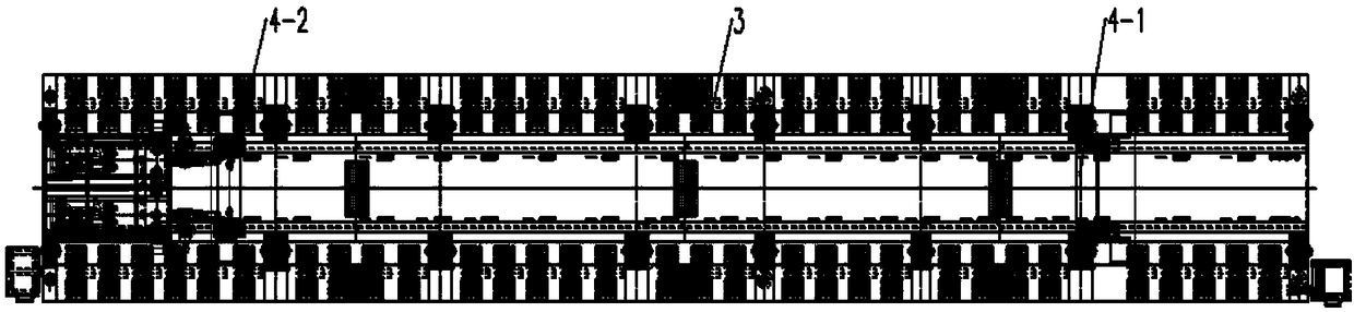
[0044] The U-shaped tunnel beam transport vehicle with adjustable wheelbase at least includes a vehicle body 1 , a walking wheel set 2 , a steering system 3 and a beam trolley 4 . Among them, see Figure 4-6 , the car body 1 is a U-shaped structure, the walking wheel set 2 and the steering system 3 are located under the car body, and form a detachable connection with the car body, and a plurality of hydraulic legs can also be provided under the car body , the beam trolley 4 is located on the car body 1.
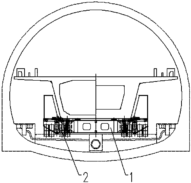
[0045] see image 3 , shows the end view of the U-shaped tunnel beam transport vehicle with adjustable wheelbase of the present invention carrying the box girder through the tunnel. ...
PUM
 Abstract
Description
Claims
Application Information