

Draught fan noise reduction worm tongue
A volute tongue and noise reduction technology, which is applied in mechanical equipment, machines/engines, liquid fuel engines, etc., can solve the problems of difficult volute tongue processing, increased noise, and increased volute tongue manufacturing costs, and achieve noise reduction and noise reduction effects Good, simple structure effect
- Summary
- Abstract
- Description
- Claims
- Application Information
AI Technical Summary
Problems solved by technology
Method used
Image

Examples
Embodiment 1
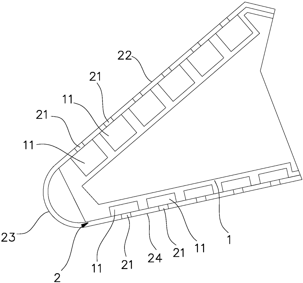
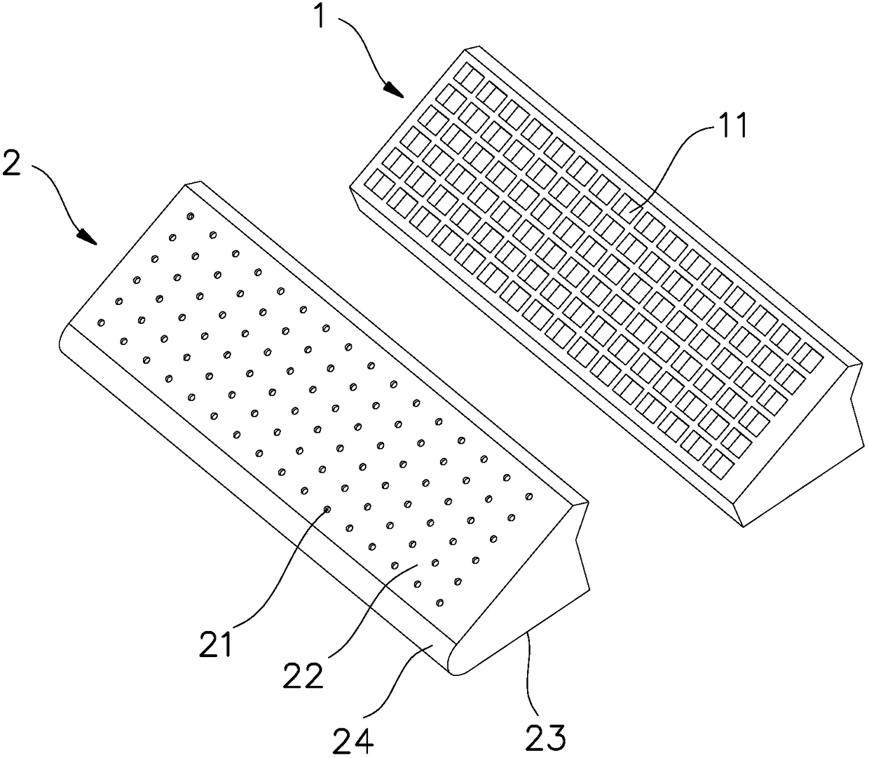
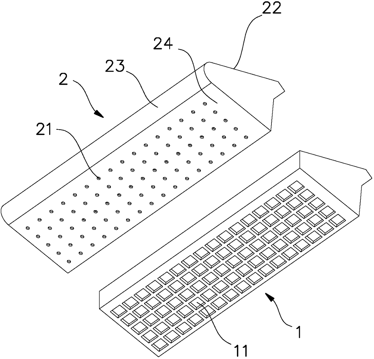
[0026] Such as Figure 1 to Figure 6 As shown, the fan noise-reducing volute tongue in this embodiment includes a volute tongue body 1 and an outer cover 2 which is arranged outside the volute tongue body. match. Wherein, the upper side and the lower side of the volute tongue body 1 are provided with a noise reduction chamber 11, and the noise reduction chamber 11 on the upper side forms a diversion noise reduction chamber, and the noise reduction chamber 11 on the lower side forms a return flow noise reduction chamber Correspondingly, the upper side of the outer cover 2 forms the diversion surface 22, and the lower side of the outer cover 2 forms the return flow surface 23, and on the diversion surface 22, there are noise reduction holes 21 corresponding to the diversion noise reduction cavity one by one. The surface 23 is provided with noise reduction holes 21 corresponding to the return flow noise reduction chambers one by one. In addition, the flow-guiding surface 22 and...
Embodiment 2
[0032] Such as Figure 7 As shown, the variation trend of the volume V of the noise reduction chamber 11 of the noise reduction volute tongue of the present embodiment is specifically as follows: the cross-sectional areas of the noise reduction chambers 11 on the same side are equal in size, and the noise reduction chambers located on the same side of the volute tongue body 1 The depth of the chamber 11 gradually increases from the position corresponding to the impeller middle plate to the front and rear sides of the volute tongue, that is, the depth of the noise reduction chamber 11 near C2 is the smallest, and gradually increases along the direction indicated by the arrow A2. The rest of the structure is the same as that of Embodiment 1, and will not be further described here.
Embodiment 3
[0034] Such as Figure 8 As shown, the volume of the noise reduction cavity 11 located on the same side of the volute body 1 of the noise reduction volute tongue of this embodiment is equal, and the area S of the noise reduction hole 21 located on the same side of the outer cover 2 corresponds to the middle plate of the impeller. The position gradually becomes smaller towards the front and rear sides of the cochlear tongue. That is, the area S of the noise reduction hole near C3 is the largest, and gradually decreases along the direction indicated by the arrow A3.
PUM
 Abstract
Description
Claims
Application Information