Deep foundation pit deformation distribution type monitoring system based on OFDR technology

A distributed monitoring and deep foundation pit technology, applied in the field of foundation soil survey, foundation structure test, foundation structure engineering, etc., can solve the problems of low survival rate of measurement points, inability to achieve real-time monitoring, limited data collection, etc. , to achieve high sensitivity and spatial resolution, lower engineering monitoring costs, and low R&D and manufacturing costs

Inactive Publication Date: 2018-07-06
HOHAI UNIV
View PDF5 Cites 10 Cited by
  • Summary
  • Abstract
  • Description
  • Claims
  • Application Information

AI Technical Summary

Problems solved by technology

The horizontal displacement of the deep soil in the foundation pit, the groundwater level, and the supporting axial force are the three important aspects of foundation pit monitoring. At present, the monitoring of these three items mainly uses traditional manpower and electronic equipment such as inclinometers, water level gauges, and steel axial force gauges. These methods have the following limitations and deficiencies: (1) Most of them are point-based measurements, and the data collected is limited, which is prone to missed detection and cannot fully reflect the deformation characteristics of the monitored objects; (2) The consumption of manpower is large,

Method used


Image

  • Deep foundation pit deformation distribution type monitoring system based on OFDR technology
  • Deep foundation pit deformation distribution type monitoring system based on OFDR technology
  • Deep foundation pit deformation distribution type monitoring system based on OFDR technology

Examples


Embodiment

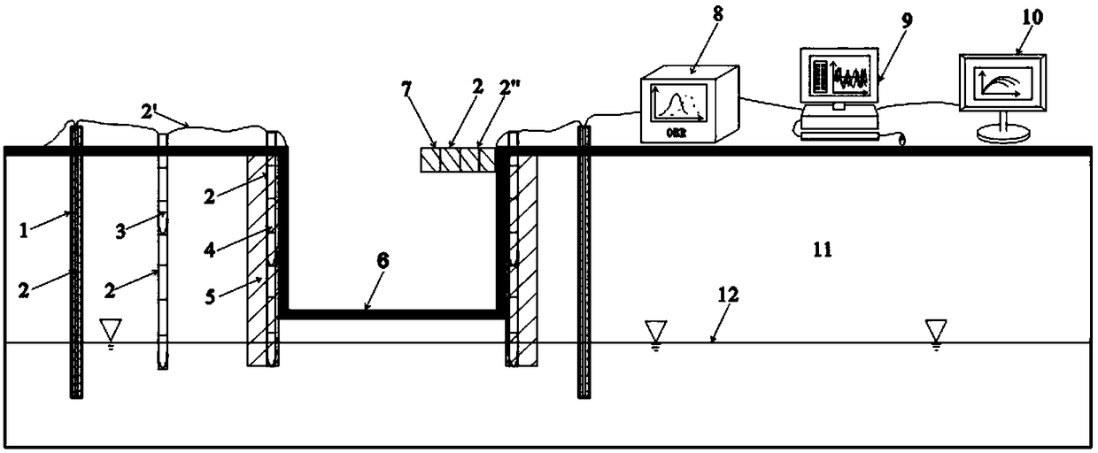
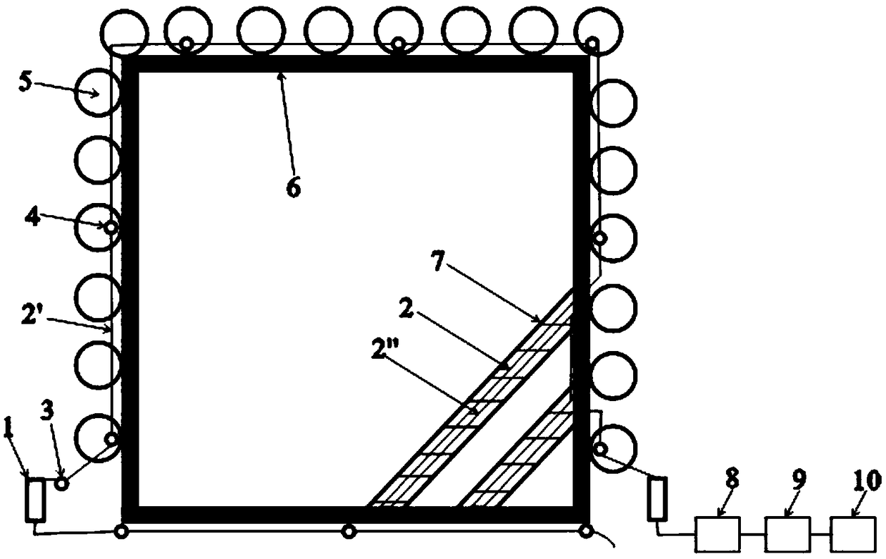
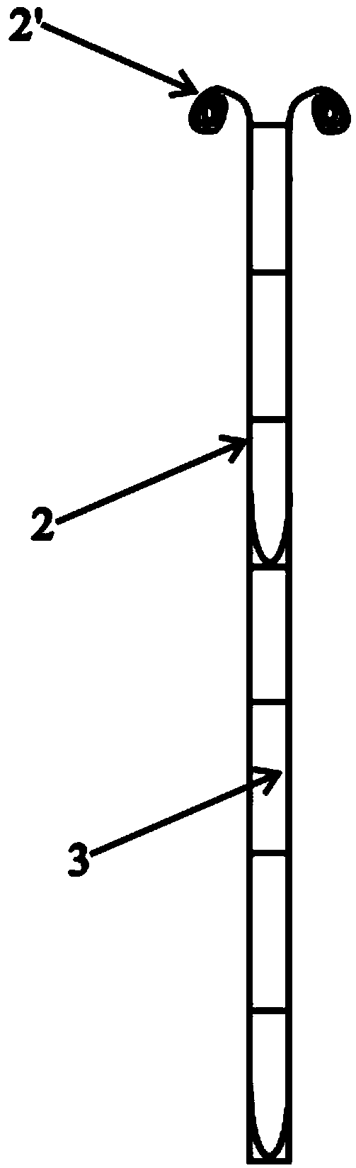
[0031] The overall cross-sectional schematic diagram of this embodiment is as figure 1 as shown, figure 1 Among them, 1 is a distributed optical fiber water level gauge, and the details are as follows Figure 4 As shown, the optical fiber is placed in the groove in the middle of the tape in a small U shape. The depth of the groove is 1.5mm. There are scales on both ends of the tape. Meet different engineering needs. The end of the optical fiber is aligned with the bottom of the scale, and the optical fiber is arranged in a U shape. On the one hand, the monitoring data on the left and right sides can be obtained in one measurement, and the average value of the two can reduce the measurement error. On the other hand, the U-shaped arrangement enables the water level gauge to Connect with adjacent optical fibers to facilitate the formation of a monitoring network. 2 is PE optical fiber, which is directly sealed into the groove of the soft ruler with adhesive during laying, with...


PUM


Abstract

The invention discloses a deep foundation pit deformation distribution type monitoring system based on an OFDR technology. The monitoring system comprises three optical fiber devices, namely a distribution type optical fiber inclinometer pipe, a distribution type optical fiber axial force meter and a distribution type optical fiber water level gauge, and three subsystems, namely an optical fiber data acquisition and transmission system, an optical fiber data processing and analysis system and a monitoring result display system. After all parts of optical fibers are distributed, the adjacent optical fibers are sequentially connected, forming a deep foundation pit deformation distribution type monitoring network. When data is acquired, as long as an optical fiber terminal is connected to anOBR data acquisition unit, the strain and temperature variation data of all monitored targets can be obtained by one acquisition. Then, the data is automatically processed by an OBR data processing system, the deformation, axial force and position information of the corresponding targets are obtained, and the information is displayed in the display system in a visual form, such as a chart. The method has the advantages of high precision, high efficiency, wide range, simple operation and the like.

Description

technical field [0001] The invention belongs to the field of geotechnical engineering monitoring, and in particular relates to a distributed monitoring system for deep foundation pit deformation based on OFDR technology. Background technique [0002] With the construction of a large number of high-rise buildings and underground infrastructure, the number of foundation pits continues to increase and the scale continues to expand. How to effectively monitor the deformation of foundation pits during construction and ensure the safety and stability of foundation pits has become the focus of attention and research hotspots in the engineering community. The horizontal displacement of the deep soil in the foundation pit, the groundwater level, and the supporting axial force are the three important aspects of foundation pit monitoring. At present, the monitoring of these three items mainly uses traditional manpower and electronic equipment such as inclinometers, water level gauges, a...

Claims


Application Information

Patent Timeline
IPC IPC(8): E02D1/02E02D33/00
CPCE02D1/022E02D33/00E02D2600/10
Inventor 高磊龚云皓胡国辉胡艳杰
Owner HOHAI UNIV
Why Eureka
Try Eureka