OBR-based prefabricated pile body stress-strain monitoring system and using method

A stress-strain monitoring system technology, applied in the direction of force measurement, measurement force, measurement device, etc. by measuring the change of optical properties of materials when they are stressed, can solve the problem of complex fabrication process, high price, spatial resolution and poor quality of FBG sensors. The problem of low monitoring accuracy is to achieve the effect of reducing engineering monitoring costs, low R&D and manufacturing costs, and realizing automatic processing.

Inactive Publication Date: 2017-05-17
HOHAI UNIV
View PDF3 Cites 4 Cited by
  • Summary
  • Abstract
  • Description
  • Claims
  • Application Information

AI Technical Summary

Problems solved by technology

In current scientific research tests and engineering construction, traditional electrical strain gauges are mainly used to monitor the strain of prefabricated piles. The installation and layout of strain gauges are cumbersome, the survival rate of measuring points is low, and the monitoring data is not continuous.
In the case of too many strain gauges, multiple strain gauge data lines must be derived along the pile body, the monitoring efficiency is low, and it is difficult to better meet the needs of scientific research and engineering
Among the existing pile strain monitoring methods based on optical fiber technology, there are mainly FBG technology, BOTDR technology and BOFDA technology. Distributed monitoring technology, but the spatial resolution and monitoring accuracy are not high, which cannot meet the monitoring needs of some scientific research experiments and engineering construction

Method used


Image

  • OBR-based prefabricated pile body stress-strain monitoring system and using method
  • OBR-based prefabricated pile body stress-strain monitoring system and using method
  • OBR-based prefabricated pile body stress-strain monitoring system and using method

Examples


Embodiment

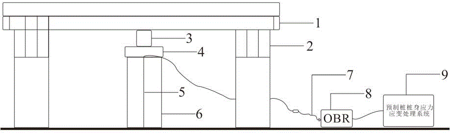
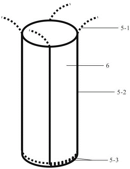
[0035] The overall structure schematic diagram of this embodiment is as follows figure 1 As shown, the entire monitoring system is divided into three modules, the loading and applying module, the optical fiber laying module, and the acquisition and processing module. 1 is an I-shaped rigid beam, 2 is a steel bar connecting the steel plate and the surrounding pile, and the connection method is welding, and 3 is a jack. 4 is rigid backing plate, and size is suitable with pile diameter. 5 is an optical fiber, using PE optical fiber, 6 is a test pile, and 7 is an optical fiber jumper, which is used to connect the optical fiber to be tested with the OBR data acquisition instrument, and the optical fiber to be tested is fused with an optical fiber fusion splicer. 8 is an OBR data acquisition instrument, including an optical fiber data acquisition system and an optical fiber signal data acquisition system, and 9 is a prefabricated pile body stress and strain processing system.

[...


PUM


Abstract

The invention discloses an OBR-based prefabricated pile body stress-strain monitoring system and a using method. The system includes a vertical load applying module, an optical fiber layout module and a data acquisition module. The vertical load applying module uses a reaction frame and a jack to apply a reaction force. The optical fiber layout module uses PE optical fibers and a tailored bonding agent. The optical fibers are disposed on the prefabricated pile body in a U-shape so as to achieve self-compensation of the temperature of the optical fibers. The data acquisition module uses an OBR data meter to acquire initial data, and uses a prefabricated pile body stress-strain processing system to further process the acquired data and finally obtains a stress-strain curve of the pre-fabricated pile body. The system uses OBR optical frequency domain technology that is the most advanced currently in the industry, so that the monitoring can achieve the sensitivity of backscattering level and the spatial resolution of millimeter level. The system can also automatically process monitoring data by using the pre-fabricated pile body stress-strain processing system, so that the system has high precision and is highly intelligent, is easy to implement, requires low manpower and cost, and can achieve damage-free detection and real-time monitoring.

Description

technical field [0001] The invention relates to a deformation monitoring device and method of a foundation structure, in particular to a prefabricated pile body stress and strain monitoring system based on OBR technology and a method for using it. Background technique [0002] Prefabricated piles have been widely used in engineering due to their advantages such as good pile quality, high construction efficiency, and large bearing capacity per unit area. The study of the stress-strain relationship of prefabricated piles under vertical loads is very important for determining the bearing capacity of prefabricated piles and promoting them. The use of prefabricated piles plays an important role. In current scientific research experiments and engineering construction, traditional electrical strain gauges are mainly used to monitor the strain of prefabricated piles. The installation and layout of strain gauges are cumbersome, the survival rate of measuring points is low, and the mo...

Claims


Application Information

Patent Timeline
IPC IPC(8): G01B11/16G01L1/24
CPCG01B11/16G01L1/242
Inventor 高磊龚云皓余彦杰宋涵韬姚悦胡国辉
Owner HOHAI UNIV
Why Eureka
Try Eureka