
Face structure light scanning apparatus

A scanning device and surface structured light technology, applied in the field of measuring instruments, can solve the problems of slow measurement speed, inability to measure black objects and reflective objects, cumbersome operation, etc., and achieve convenient installation and unloading, stable and compact structure, and large measurement area Effect

Inactive Publication Date: 2007-12-05
HUAZHONG UNIV OF SCI & TECH
View PDF0 Cites 9 Cited by
  • Summary
  • Abstract
  • Description
  • Claims
  • Application Information

AI Technical Summary

Problems solved by technology

[0004] The contact-type three-coordinate measuring machine has high precision, but it can only measure one point at a time, the measurement speed is slow, it is difficult to design curved surfaces, it cannot measure soft objects, and the operation is cumbersome
[0005] The 3D laser scanning measuring instrument is bulky and requires a large platform, the accuracy and speed are limited, and the measurement range is also limited by the platform size of the measuring instrument
[0006] The grating type three-dimensional measuring instrument uses the grating as the light source, and the measurement speed is fast, but the measurement method is limited by the surface color of the object, and cannot measure black objects and reflective objects

Method used


Image

  • Face structure light scanning apparatus
  • Face structure light scanning apparatus
  • Face structure light scanning apparatus

Examples


Embodiment Construction

[0013] The present invention will be described in further detail below according to the accompanying drawings and examples.

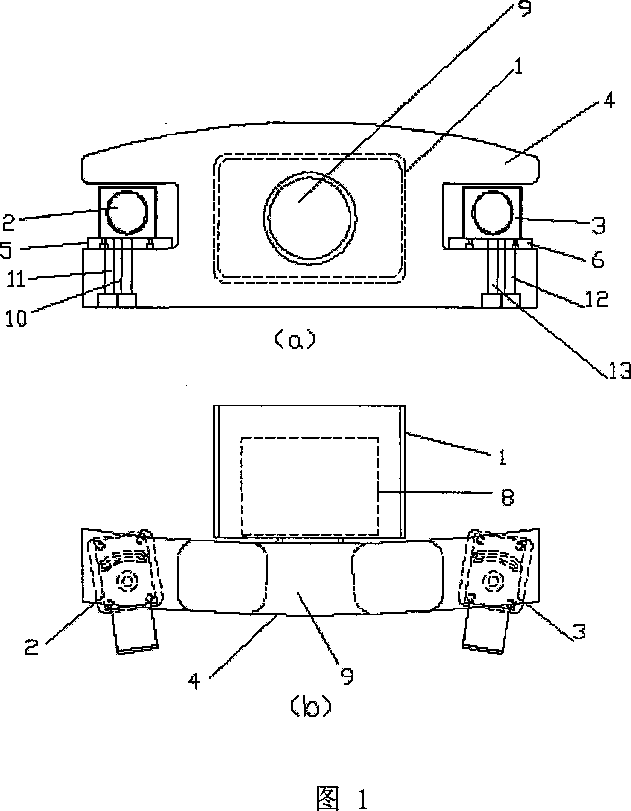
[0014] As shown in FIG. 1 , the surface structured light scanning device of the present invention includes a left CCD camera 2 , a right CCD camera 3 and a projector 8 .

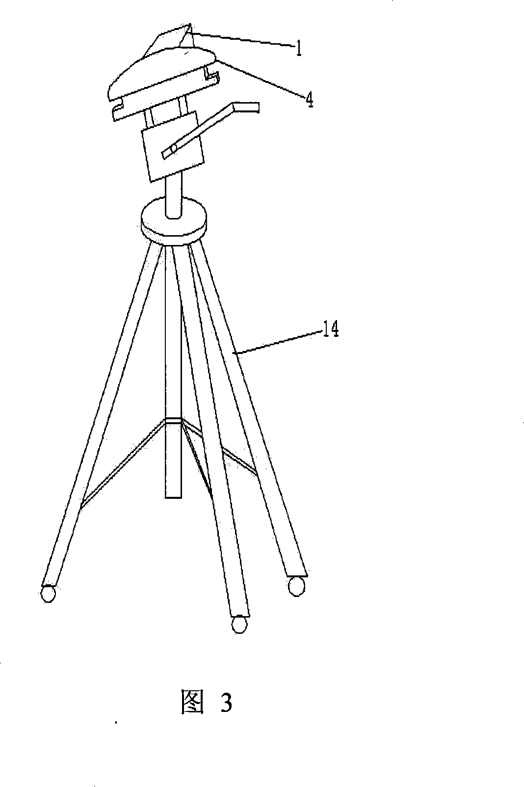
[0015] The frame 1 adopts a hollow structure, the projector 14 is located in the frame 1 , and the bottom of the frame 1 is connected with the tripod 14 .

[0016] The two ends of the mounting frame 4 are provided with through grooves, the left and right sides through grooves are of symmetrical structure, and the middle part is provided with a through hole 9 .

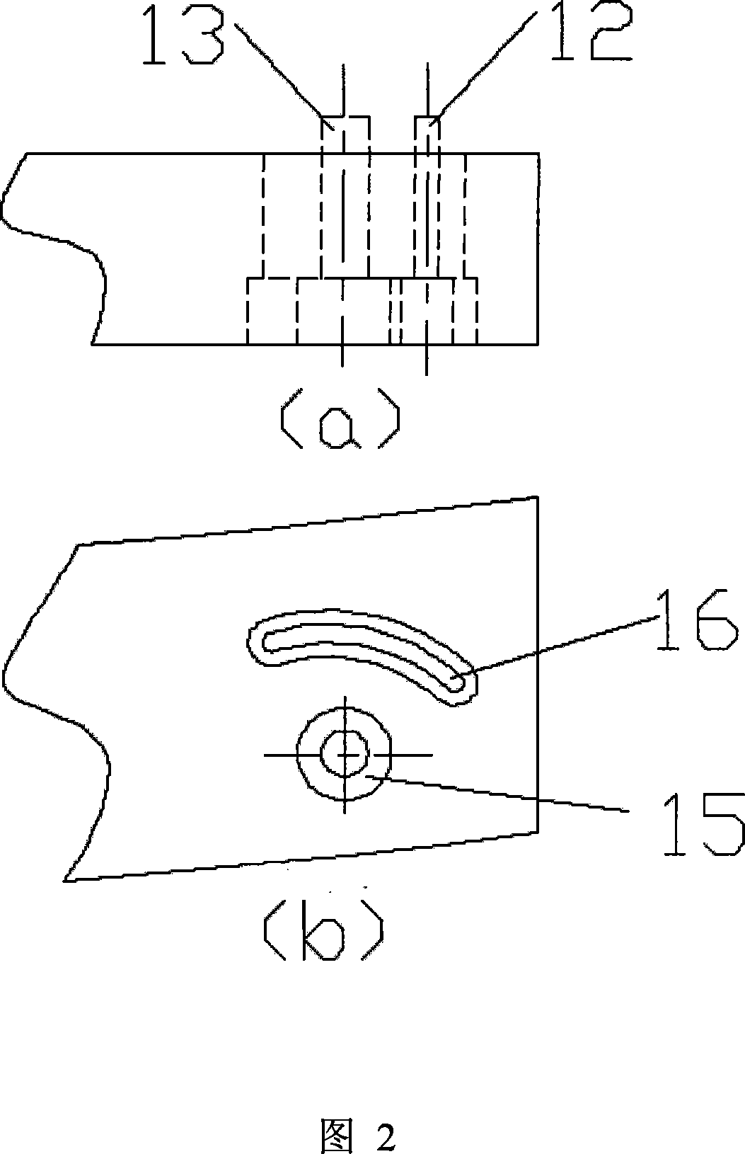
[0017] The left CCD camera head 2 is fixedly connected with the left fixed block 5, and is installed in the left through groove of the mounting frame 4 by first and second screws 10,11. The right CCD camera head 3 is fixedly connected with the right fixed block 6, and is installed in the right through groove of the installati...


PUM


Abstract

The invention discloses a light scanning device of face structure, which comprises the following parts: left CCD cam, right CCD cam and projector, wherein the projector lies in the frame; the symmetrical left and right through-grooves are set on two ends of assembling rack with through-hole in the middle; the bottom of left and right through-groove has two-step hole; the left CCD cam connects fixing block strictly, which is assembled in the two-step hole of left through-groove through first and second screws; the right CCD cam and right fixing block connect strictly, which are assembled in the two-step hole of right through-groove of assembling rack; the step hole mates the screw. The invention has stable and compact structure and convenient assemblage and unloading with adjustable measuring scale through modularized assembling rack, which can satisfies the need of backward engineering and precision detection.

Description

technical field [0001] The invention relates to a measuring instrument for reverse engineering, in particular to a surface structured light scanning device for reverse engineering. Background technique [0002] Reverse engineering plays an important role in shortening the product design cycle and assimilating advanced technologies and products at home and abroad. The quality of reverse engineering measurement equipment directly affects the accuracy and completeness of the description of the measured entity, and then affects the quality of the reconstructed CAD surface and solid model, which is the basis of reverse engineering. [0003] At present, the most widely used measuring equipment in the field of reverse design mainly includes the following four types: contact coordinate measuring device, three-dimensional laser scanning measuring device, flexible three-dimensional coordinate measuring device, and raster scanning measuring device. The contact three-coordinate measuri...

Claims


Application Information

Patent Timeline
IPC IPC(8): G03B17/54G01B11/00G01B11/03G01B11/24G01C11/00
Inventor 王从军周钢李中伟朱本璋李晓宁杨彪杜俊贤
Owner HUAZHONG UNIV OF SCI & TECH
Learn More