A pulse shock frequency generator

A generator and pulse technology, which is applied in the field of pulse seismic frequency generators, can solve problems such as lack of understanding, inability to release jams, insufficient shock frequency and intensity, etc., to improve fluid properties, increase drilling time efficiency, and reduce fishing difficulty. Effect

Active Publication Date: 2020-03-17
程显达 +1
View PDF8 Cites 0 Cited by
  • Summary
  • Abstract
  • Description
  • Claims
  • Application Information

AI Technical Summary

Problems solved by technology

[0003] At present, there is no continuous jarring booster acceleration device for oil drilling; moreover, although various types of jars have been developed for workover and salvage jamming at the construction site, due to their lack of understanding of jarring jamming, many Type jars cannot be jammed during the jamming process due to insufficient jarring frequency and strength or improper technological measures; at the same time, there is no integrated equipment for oil production pulse deblocking, increasing penetration, increasing production and oil production during the oil recovery process

Method used


Image

  • A pulse shock frequency generator
  • A pulse shock frequency generator
  • A pulse shock frequency generator

Examples


Embodiment 1

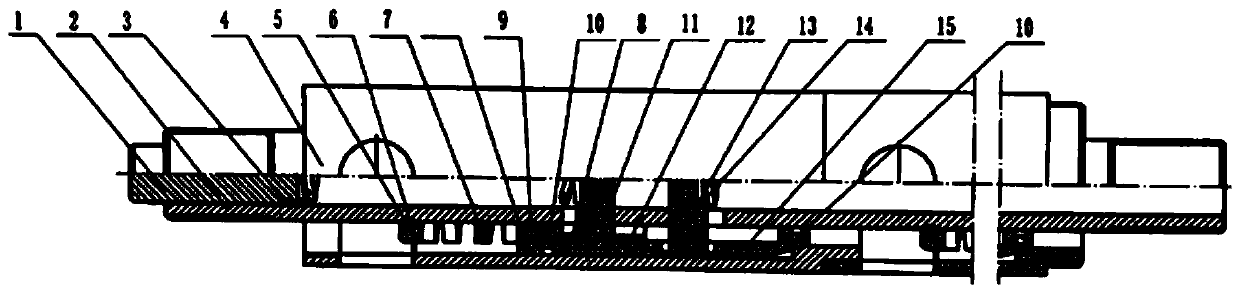
[0029] Such as figure 1 As shown, this embodiment provides a pulse shock frequency generator, which includes: a hydraulic cylinder, a connecting rod, a piston, and a pressure relief valve; the inside of the hydraulic cylinder is provided with a stepped hole with openings at both ends; the ladder The narrow section of the hole is a low-pressure chamber, and the wide section of the stepped hole is a high-pressure chamber; the connecting rod is arranged in the hydraulic cylinder through the stepped hole, and the two ends of the connecting rod are located outside the hydraulic cylinder , the connecting rod is matched with the high-pressure chamber and the low-pressure chamber; the piston and the pressure relief valve are sleeved on the connecting rod and placed in the hydraulic cylinder; the connecting rod is provided with a piston A guide hole and a pressure relief valve guide hole, and the piston guide hole is provided with a piston pin, and the pressure relief valve guide hole ...

Embodiment 2

[0042] This embodiment provides a pulse shock frequency generator combined in series with multi-stage hydraulic cylinders, which includes a connecting rod and at least two hydraulic cylinders, and the hydraulic cylinders are all sleeved outside the connecting rod and combined in series; the two connecting rods The ends are respectively located outside the liquid cylinders at both ends, and the high pressure chamber of each liquid cylinder is hung with a piston and a pressure relief valve.

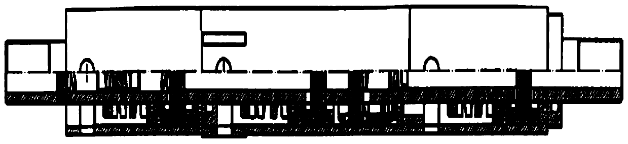
[0043] Specifically, such as figure 2 As shown, the number of hydraulic cylinders is two, namely the first hydraulic cylinder and the second hydraulic cylinder; the first hydraulic cylinder and the second hydraulic cylinder are combined in series and sleeved on the connecting rod, and the two ends of the connecting rod are respectively located at outside the first and second cylinders.

[0044] Wherein, the structure of the first liquid cylinder and the second liquid cylinder is the same ...

Embodiment 3

[0046] Such as image 3 As shown, this embodiment provides a pulse vibration frequency generator combined in series with a master cylinder and a slave cylinder, which includes a connecting rod, a first slave cylinder, a master cylinder and a second slave cylinder; the first slave cylinder The cylinder, the master cylinder and the second slave cylinder are sequentially combined in series and sleeved on the connecting rod; the two ends of the connecting rod are located outside the first slave cylinder and the second slave cylinder respectively.

[0047] Wherein, the structure of the first active cylinder is the same as that of the hydraulic cylinder in Embodiment 1, and the first active cylinder is provided with a piston and a pressure relief valve, and the structure and arrangement of the piston and hydraulic valve are the same as those of the piston and pressure relief valve in Embodiment 1. The structure and setting method of the pressure relief valve.

[0048] The inside of...


PUM


Abstract

The invention relates to a pulse shock frequency generator. The pulse shock frequency generator comprises a liquid cylinder, a connecting rod, a piston and a pressure relief valve. The connecting rodis arranged in the liquid cylinder. The piston and the pressure relief valve are arranged on the connecting rod in a sleeving mode. The connecting rod is provided with a piston guide hole and a pressure relief valve guide hole. The pressure relief valve is arranged at the pressure relief valve guide hole in a hung mode and used for controlling opening and closing of a pressure relief opening of the liquid cylinder. The piston is arranged at the piston guide hole in a hung mode. The connecting rod is provided with a liquid inlet hole. According to the pulse shock frequency generator, mechanicalpulse shock waves can be produced through up-down reciprocating movement of the connecting rod; meanwhile, liquid of the liquid cylinder also produces pulse waves to be sprayed out of the liquid cylinder; therefore, the pulse shock frequency generator is widely used in various practical production areas such as mine mining, piling, equipment breaking-demolition and vibration tests, especially thepulse shock frequency generator plays an important role and application in oil exploitation, the difficulty of oil production is reduced, and the permeability of stratum rock is increased; breaking of the stratum rock is accelerated, the drilling speed of a drill bit is increased, and drilling aging is improved; and the salvage lifting load is reduced, and the salvage and unfreezing efficiency isimproved.

Description

technical field [0001] The invention belongs to the technical field of shock devices, and in particular relates to a pulse shock frequency generator. Background technique [0002] During drilling and workover operations, due to the properties of drilling fluid, geological conditions and long-term high-intensity mining, etc., the rock cement strength is reduced or destroyed, and the formation is sanded or collapsed, resulting in downhole sticking. Especially in oilfield development, the long-term water injection development has accelerated the reduction of formation cementation strength in the development well section in the middle and late stages of oilfield development. The quickest way is to remove the card by activity. [0003] At present, there is no continuous jarring booster acceleration device for oil drilling; moreover, although various types of jars have been developed for workover and salvage jamming at the construction site, due to their lack of understanding of ...

Claims


Application Information

Patent Timeline
Patent Type & Authority Patents(China)
IPC IPC(8): E21B28/00
CPCE21B28/00
Inventor 程显达代煜斐
Owner 程显达
Why Eureka
Try Eureka