Centrifugal pump

A centrifugal pump and casing technology, applied in the field of machinery, can solve the problems of inconvenient cleaning, inconvenient and flexible installation of centrifugal pumps, weak centrifugal efficiency, etc., and achieve the effects of easy disassembly and cleaning, improving the scope of use, and avoiding large shocks.

Inactive Publication Date: 2018-07-06
湖州诺诚低温设备有限公司
View PDF0 Cites 1 Cited by
  • Summary
  • Abstract
  • Description
  • Claims
  • Application Information

AI Technical Summary

Problems solved by technology

[0004] In view of this, what this application intends to solve is the technical problems that centrifugal pumps in the conventional technology are not convenient for flexible installation, the centrifugal efficiency is easily weakened and it is not convenient to clean impurities

Method used


Image

  • Centrifugal pump
  • Centrifugal pump
  • Centrifugal pump

Examples


Embodiment Construction

[0023] The embodiments of the present application will be described in detail below with reference to the accompanying drawings and examples, so as to fully understand and implement the implementation process of how to apply technical means to solve technical problems and achieve technical effects in the present application.

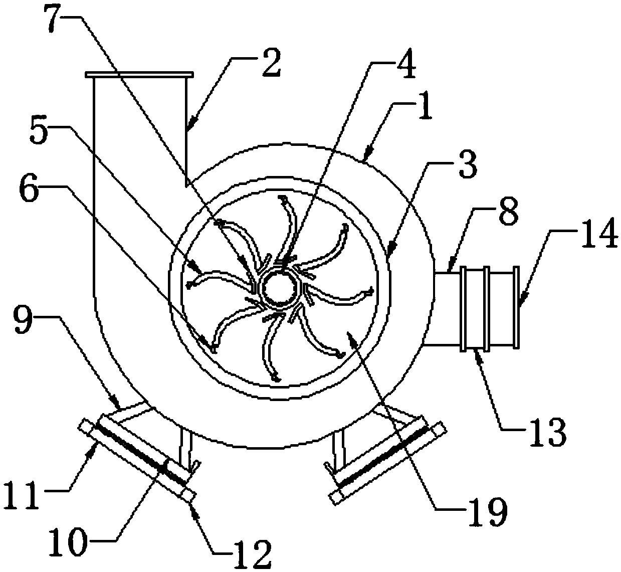
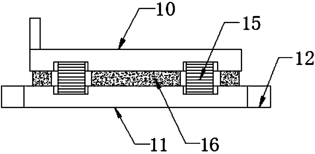
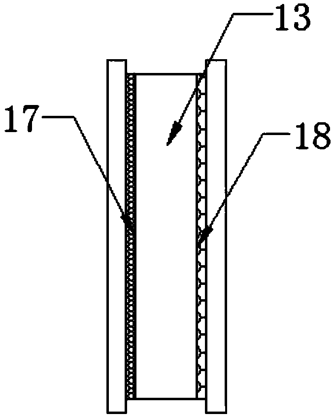
[0024] like Figure 1-4 As shown in the figure, a centrifugal pump of the present invention includes: a casing 1, a water outlet 2 and a cover plate 19, a water outlet 2 is provided on one side of the casing 1, a cover plate 19 is arranged inside the casing 1, and the cover plate 19 A connecting shaft sleeve 4 is arranged at the center of the cover plate 19, and several arc-shaped blades 5 are evenly arranged on both sides of the cover plate 19. Some two pairs of support rods 9 are connected with a shock-absorbing mounting seat mechanism, the other side of the housing 1 is provided with a water inlet 8, and one side of the water inlet 8 is provided with ...


PUM


Abstract

The invention discloses a centrifugal pump which comprises a shell, a water outlet and a cover plate, wherein the water outlet is formed in one side of the shell, the cover plate is arranged in the shell, a connecting axle sleeve is arranged at the center of the cover plate, a plurality of arc blades are uniformly arranged at two sides of the cover plate, an arc head is fixed at one end of each ofthe arc blades, a damping mounting seat mechanism is connected to two sides of the bottom of the shell by two pairs of support rods which are hinged, a water inlet is formed in the other side of theshell, and a filtering mechanism is arranged at one side of the water inlet. According to the scheme, an arc water guide plate arranged at one end of the arc blade can guide water, so as to prevent water flowing to the connecting sleeve from flowing without restraint to reduce the centrifugal strength, and the design of an annular water blowing plate can reduce resistance of the cover plate to water after entering the shell, so as to improve the centrifugal efficiency; and due to the design of the damping mounting seat mechanism, the mounting angle can be changed flexibly according to mountingarea, so as to extent the use scope.

Description

technical field [0001] The present application belongs to the technical field of machinery, and in particular, relates to a centrifugal pump. Background technique [0002] Before the pump works, the pump body and the water inlet pipe must be filled with water, and then rely on the high-speed rotating impeller, so that the liquid can obtain energy under the action of inertial centrifugal force, thereby increasing its internal pressure. When the impeller rotates rapidly, the blades make the water rotate quickly. , the rotating water flies away from the impeller under the action of centrifugal force. After the water in the pump is thrown out, the central part of the impeller forms a vacuum area, and then the water from the water source passes through the tube under the action of atmospheric pressure (or water pressure). The net is pressed into the water inlet pipe, so that the circulation is endless, and continuous water pumping can be realized. [0003] When the traditional c...

Claims


Application Information

Patent Timeline
Patent Type & Authority Applications(China)
IPC IPC(8): F04D1/00F04D29/44F04D29/62F04D29/66F04D29/70
CPCF04D1/00F04D29/445F04D29/628F04D29/669F04D29/708
Inventor 汤国强
Owner 湖州诺诚低温设备有限公司
Why Eureka
Try Eureka