Signal testing device

A technology for signal testing and test fixtures, applied in the computer field, can solve problems such as the inability to test connectors

Active Publication Date: 2018-07-06
中科曙光信息产业成都有限公司 +1
View PDF3 Cites 2 Cited by
  • Summary
  • Abstract
  • Description
  • Claims
  • Application Information

AI Technical Summary

Problems solved by technology

However, due to the large number of current PCIE signal interface co

Method used


Image

  • Signal testing device
  • Signal testing device

Examples


Embodiment Construction

[0019] The following will clearly and completely describe the technical solutions in the embodiments of the present invention with reference to the accompanying drawings in the embodiments of the present invention. Obviously, the described embodiments are only some, not all, embodiments of the present invention. All other embodiments obtained by persons of ordinary skill in the art based on the embodiments of the present invention belong to the protection scope of the present invention.

[0020] According to an embodiment of the present invention, a signal testing device is provided.

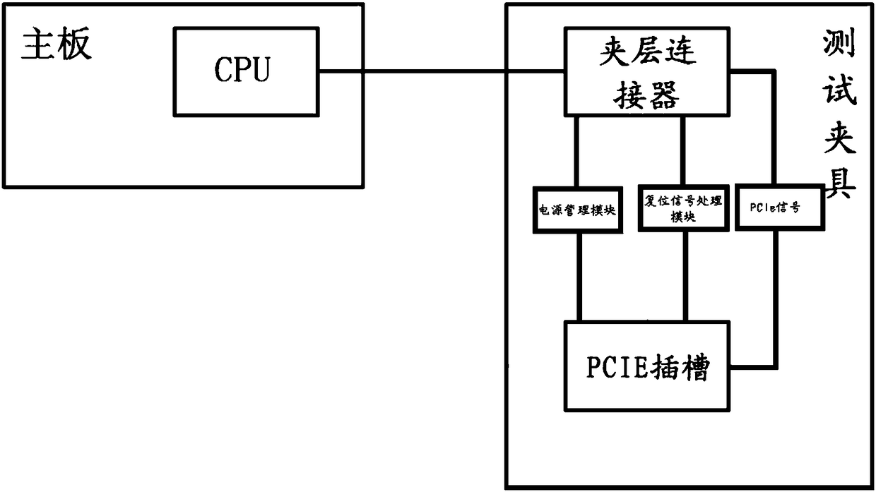
[0021] Such as figure 1 As shown, the signal test device according to the embodiment of the present invention includes: a mainboard, a test fixture, and the test fixture is connected to the mainboard; wherein, the test fixture includes: a mezzanine connector, a PCIE slot, a mezzanine connector and a mainboard connection, and a mezzanine connector It is also connected to the PCIE slot.

[0022]...


PUM


Abstract

The invention discloses a signal testing device. The device comprises a main board and a testing clamp, wherein the testing clamp is connected with the main board; the testing clamp comprises an interlayer connector and a PCIE slot, the interlayer connector is connected with the main board, and the interlayer connector is further connected with the PCIE slot. According to the device, the interlayer connector is connected with the PCIE slot so that various testing of non-standard PCIE interface signals of the interlayer connector can be achieved through the designed testing clamp, and the signal integrity of a communication link can be effectively ensured.

Description

technical field [0001] The invention relates to the field of computers, in particular to a signal testing device. Background technique [0002] MEG-Array connector (or mezzanine connector) is a high-speed, high-density array connector with a communication rate of up to 10Gbps. It is currently widely used in the field of high-speed signal link design of computer systems. In addition, CPU (Central Processing Unit, central processing unit) and GPU (Graphics Processing Unit, graphics processing unit) generally communicate through PCIE (Peripheral Component Interconnect Express, the latest bus and interface standard) protocol interface, MEG-Array connector Generally, it is the first choice for designing communication between GPU and computer, which can meet the needs of high-speed signal transmission. However, because the MEG-Array connector is an array interface with high signal density, it is difficult to pass spot testing and other methods, and the accuracy and accuracy of te...

Claims


Application Information

Patent Timeline
IPC IPC(8): G06F11/22
CPCG06F11/221G06F11/2273
Inventor 李东新陈进赵振伟
Owner 中科曙光信息产业成都有限公司
Why Eureka
Try Eureka